PSU Repair: A Case Study

PWM Bypass Capacitor Results

Considering the tremendous improvements from replacing the busted auxiliary cap, I am starting to have doubts about how much more replacing the controller's bypass cap might achieve: the controller seems perfectly happy drawing current from the auxiliary supply cap through its photocoupler and transistor.

Then again, the way there is effectively no ripple on the auxiliary supply while the main outputs are live using the new 100µF cap tells me the new capacitor is grossly over-sized and that the controller's 22µF cap should have been more than enough to keep it running. The fact that it did not, at least not without the help of several kicks in the pants to get it started, may indicate it is either busted or severely degraded, just like the auxiliary output's was.

I just so happened to have 33µF 50V FC-series caps in stock, which should be a great fit for the 22µF 50V cap on the board.
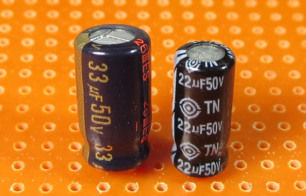
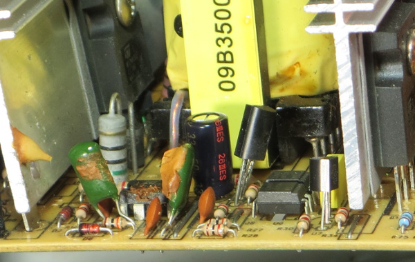
The sizes look quite similar and I have matching lead spacing, but it is not quite a perfect fit. I still had to nudge a transistor sideways to slip the 1.3mm-wider capacitor in. I call that close enough and not worth ordering replacements specifically for it, although I might still end up doing so if it helps me pad an order to get free shipping.

Unlike the previously-replaced caps, which had capacitance an order of magnitude off or worse, this one actually measured in at 18µF, not that far from its nominal 22µF.

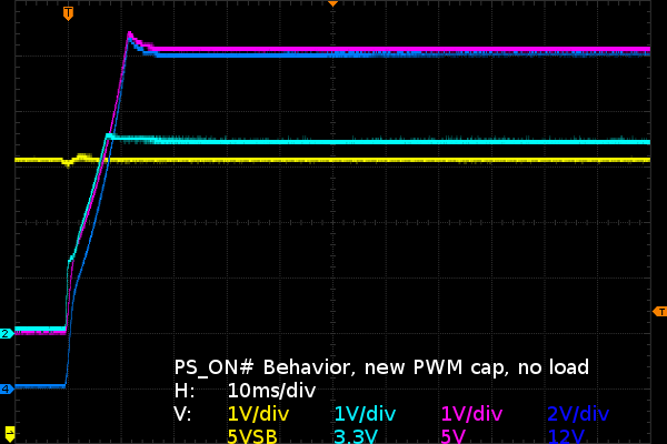
It might be difficult to tell anything has actually changed from the PS_ON# behavior. There is only one tiny detail to give it away: a small dip on the 5VSB output just before the main converter starts operating. This would be the PWM's bypass capacitor charging up, momentarily dragging the auxiliary and 5VSB outputs down slightly.
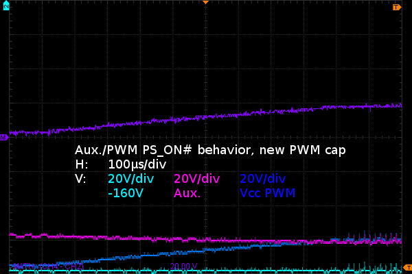
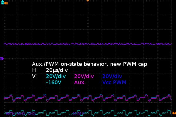
On the primary side, there is only one obvious change: whereas the old cap “charged up” to the auxiliary supply's voltage in a matter of maybe 10µs during the PS_ON# sequence, the new capacitor takes almost a whole millisecond to do the same, a hundred times longer, to reach its 20V operating point. While the old cap's nominal capacitance may have been marginally good, its series resistance must have been horrible for it to have effectively no effect on circuit operation.

During the steady on-state, I cannot honestly say I see any difference on my primary-side signals from the new bypass capacitor. The signals look slightly cleaner but at the resolution these screen captures were made at, differences are at the noise floor.

Daniel Sauvageau is a Contributing Writer for Tom's Hardware US. He’s known for his feature tear-downs of components and peripherals.
  • Nuckles_56
    An interesting read, it was interesting following the process you used to troubleshoot the problem
    Reply
  • Crashman
    I used to do this for a living :)

    Don't tell my boss, I've managed to convince him that I'm only an expert at running benchmarks and writing about the results :)
    Reply
  • epsiloneri
    Disclaimers won't help. The people who will likely hurt themselves trying this are the same who lack the reading comprehension and self awareness to understand those disclaimers are directed at them. I admire you courage in publishing this.
    Reply
  • beetlejuicegr
    the truth is the paper clip and multimeter is all i can go in to psus. after all i haven't studied electricity or circuits or whatever.
    However i do hate to throw stuff earlier than it should, like you.
    Reply
  • C12Friedman
    I like this article and I fully agree with the conclusion. I've repaired a few PSU's but, for the most part I scavenge them anymore since I can't put them in a new system (nor would I want to) IMO they aren't really worth anything other than for on a test bench.
    Reply
  • Mr A
    Daniel, I know next to nothing about electronics, and yet I could not stop reading this article. Fascinating! Thanks very much!
    Reply
  • Urzu1000
    This was a great article! It was informative, as well as interesting. Personally, I've only had one PSU fail on me so far. My brother-in-law's self-built computer had a really low-end Thermaltake PSU. 800W Bronze, and oh man, did that thing go out in a blaze of glory. Very loud popping, and smoke, and funny smells. When I ripped it out of the computer, there were burns inside the case. Miraculously, the other components remained unharmed, so I slapped in a new PSU (750W Gold Seasonic) and fired it up.

    Still working good, but I get black soot on my hands every time I open up that case. It's a black case, so it's hard to clean it off properly.
    Reply
  • nukemaster
    Good read.

    Thanks for taking the time to document this repair.
    Reply
  • Interesting article. I would have simply replaced the entire unit. You saw how to fix the failure, but how many units were damaged that you didn't see? A ticking time bomb that will eventually send some spike to your much more valuable hardware than a 10 year old PSU. Wasteful, yes. I get it. I don't like to waste either. And if it's on marginal hardware, fine. But on primary systems I'm not willing to take the risk. I'd rather throw away a 200$ part that has a 0.05$ repair solution, than risk frying 800$+ hardware.
    Reply
  • kalmquist
    "Antec's manufacturer (Channelwell in this case) got the live and neutral wires backwards, which means that in the “off” position, the neutral line gets opened and everything on the primary side becomes live instead of neutral."

    That's really bad--I doubt it is even legal to sell a power supply wired like that. I've never bought a CWT (Channelwell) power supply, and based on this I wouldn't buy one, except perhaps for a high end model where you might gamble that the company would exercise a bit more care.
    Reply