PSU Repair: A Case Study
When your PSU won't start, most enthusiasts don't go beyond a paperclip or multimeter check. Today, we'll do a comprehensive repair of Antec's old SL300.
5VSB Capacitor Replacement
The first order of business was changing those 680µF 5VSB caps with some of my 1200µF FMs. Yes, that is overkill, but those are the smallest electrolytic caps I have in stock over 100µF. There is one little problem with this: they do not fit properly on the board due to how tightly packed other components are around them. The FM is 2mm wider and has 1.5mm-wider lead spacing.
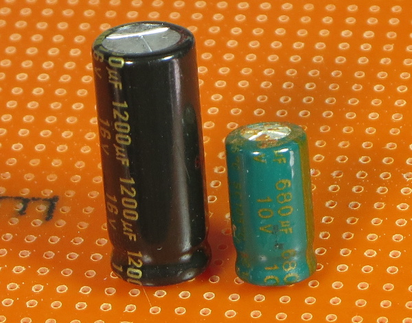
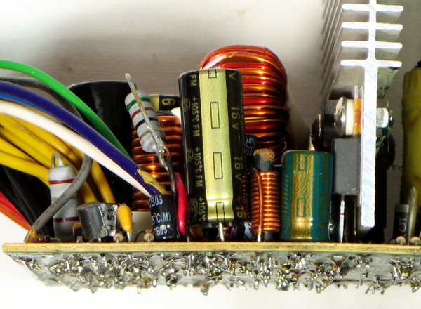
Side by side, the size difference is hard to miss. I measured the old 5VSB Teapo SC capacitors after removing them. The rear one, nearest to the heat sink and flyback transformer, read 34µF instead of the expected 680µF. Yup, that is one sick puppy. The other one still reads 600µF, which is a bit on the low side but still 15x more usable than the first.
The FM I wanted to use was an impossible fit for the critical rear capacitor's location, so I moved the hopefully still-good (enough) old cap over there for the time being. Even fitting the FM in the front cap's location required splicing wires onto the nearby dummy-load resistor to move it out of the way enough so I could get the cap reasonably close to the board.
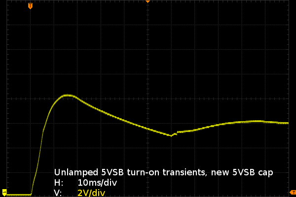
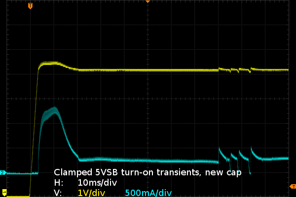
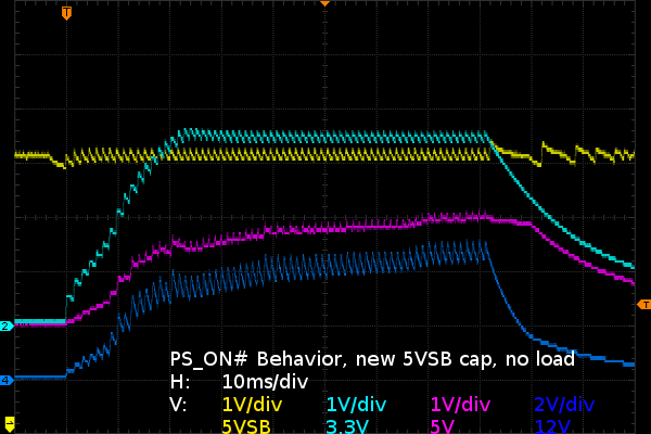
There's not a whole lot of change compared to the previous waveforms using an external capacitor on the 5VSB line. The switching noise is now almost completely gone and that is about it. The unclamped waveform still surges slightly beyond 8V and looks like it is going to settle around 6V. On the clamped waveform side, though, the surge now stops at 5.5V with the regulator shunting 1.25A before settling at 5.2V and 250mA. There are still some unexplained irregularities in the clamped 5VSB waveform that need to be looked into.
I did not take the time to fiddle with the shunt's set-point until I got a successful turn-on. All I wanted was to see what sort of effect the cap may have had on turn-on behavior. The 5VSB output is cleaner, but the main outputs' ramp-up is every bit as trashy as the previous run using the external capacitor. In other words: onward to step two of my repair plan.
Get Tom's Hardware's best news and in-depth reviews, straight to your inbox.
Current page: 5VSB Capacitor Replacement
Prev Page Setup And Safety Next Page Auxiliary Output Replacement?-
Nuckles_56 An interesting read, it was interesting following the process you used to troubleshoot the problemReply -
Crashman I used to do this for a living :)Reply
Don't tell my boss, I've managed to convince him that I'm only an expert at running benchmarks and writing about the results :) -
epsiloneri Disclaimers won't help. The people who will likely hurt themselves trying this are the same who lack the reading comprehension and self awareness to understand those disclaimers are directed at them. I admire you courage in publishing this.Reply
-
beetlejuicegr the truth is the paper clip and multimeter is all i can go in to psus. after all i haven't studied electricity or circuits or whatever.Reply
However i do hate to throw stuff earlier than it should, like you. -
C12Friedman I like this article and I fully agree with the conclusion. I've repaired a few PSU's but, for the most part I scavenge them anymore since I can't put them in a new system (nor would I want to) IMO they aren't really worth anything other than for on a test bench.Reply -
Mr A Daniel, I know next to nothing about electronics, and yet I could not stop reading this article. Fascinating! Thanks very much!Reply -
Urzu1000 This was a great article! It was informative, as well as interesting. Personally, I've only had one PSU fail on me so far. My brother-in-law's self-built computer had a really low-end Thermaltake PSU. 800W Bronze, and oh man, did that thing go out in a blaze of glory. Very loud popping, and smoke, and funny smells. When I ripped it out of the computer, there were burns inside the case. Miraculously, the other components remained unharmed, so I slapped in a new PSU (750W Gold Seasonic) and fired it up.Reply
Still working good, but I get black soot on my hands every time I open up that case. It's a black case, so it's hard to clean it off properly. -
Interesting article. I would have simply replaced the entire unit. You saw how to fix the failure, but how many units were damaged that you didn't see? A ticking time bomb that will eventually send some spike to your much more valuable hardware than a 10 year old PSU. Wasteful, yes. I get it. I don't like to waste either. And if it's on marginal hardware, fine. But on primary systems I'm not willing to take the risk. I'd rather throw away a 200$ part that has a 0.05$ repair solution, than risk frying 800$+ hardware.Reply
-
kalmquist "Antec's manufacturer (Channelwell in this case) got the live and neutral wires backwards, which means that in the “off” position, the neutral line gets opened and everything on the primary side becomes live instead of neutral."Reply
That's really bad--I doubt it is even legal to sell a power supply wired like that. I've never bought a CWT (Channelwell) power supply, and based on this I wouldn't buy one, except perhaps for a high end model where you might gamble that the company would exercise a bit more care.
