PSU Repair: A Case Study
When your PSU won't start, most enthusiasts don't go beyond a paperclip or multimeter check. Today, we'll do a comprehensive repair of Antec's old SL300.
Auxiliary Output Capacitor Replacement
Time to hit the spare parts bin again. The nearest match I have for a 47µF 25V cap is 100µF 50V Panasonic FC-series. As with the FM on the 5VSB output, the footprints and lead spacings do not match. At least this time there is plenty of clearance, so I don't need to shove things around to accommodate the larger package. I will still put something with the proper lead spacing on my next order so I can have a properly-mounted cap as my definitive fix. For troubleshooting purposes though, this is fine--a bodged cap with long leads is still better than a dead cap or no cap at all.
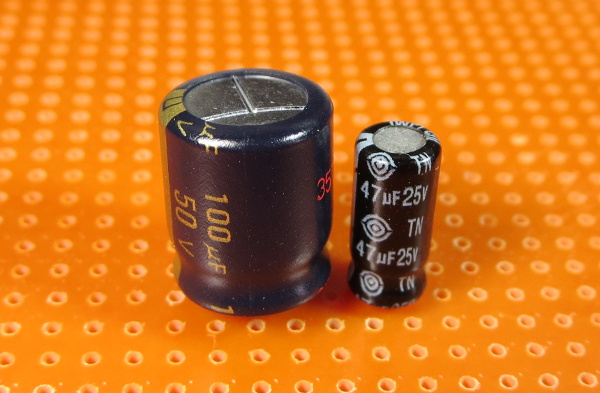
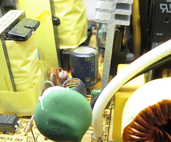
Here you can see the old cap and my replacement part; the size discrepancy is hardly subtle. When I measured that 47µF cap, it read 112pF. Yes, that's picofarads, five orders of magnitude off. The bond between the leads and the capacitor's foils or the foils themselves must have broken, corroded, fused off or something else of the sort. In any case, the capacitor reads open on the ohms range, so no internal short here either. Dead caps don't come much deader than that.
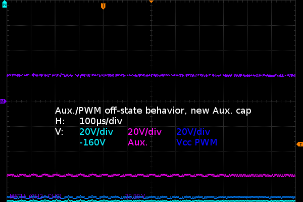
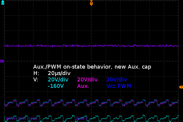
Looking at the auxiliary and PWM off-state waveforms in the first picture, I think it is quite blatantly obvious something changed. The massive noise and ripples on the auxiliary output are almost completely gone. Eliminating the auxiliary supply's massive transients also took care of those glitches on the switching controller's bypass capacitor, allowing its off-state voltage to drop lower as well.
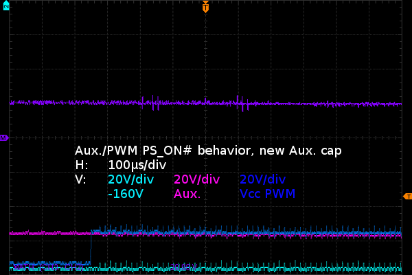
On the second picture, signs of completely different PS_ON# behavior on the auxiliary and PWM supplies are hard to miss. Instead of 20VPP worth of ripple with a lazy transition to 10VDC, we have a steady 20VDC or so on the auxiliary supply with the PWM's supply going through a sharp rise to 20V when PS_ON# comes through. There is still some amount of switching noise on the waveforms, but it is about an order of magnitude less than it was before. That's possibly better, but hard to tell at this resolution.
The last picture shows the steady on-state at a higher-resolution time scale. Whereas the old cap waveforms showed random-looking signals that had no clear relationship with the reference voltage, the auxiliary and PWM voltages are now a steady 20V above bottom cap voltage, exactly as one would expect from a capacitor charged to a certain voltage above the node it is referenced to.
With 20V DC on it during normal operation (not counting switching transients and possible output deviations), the original capacitor really should have been a 35V part, which might explain why it failed so thoroughly. Aside from that, things look very promising. This certainly looks like a major step towards a permanent fix.
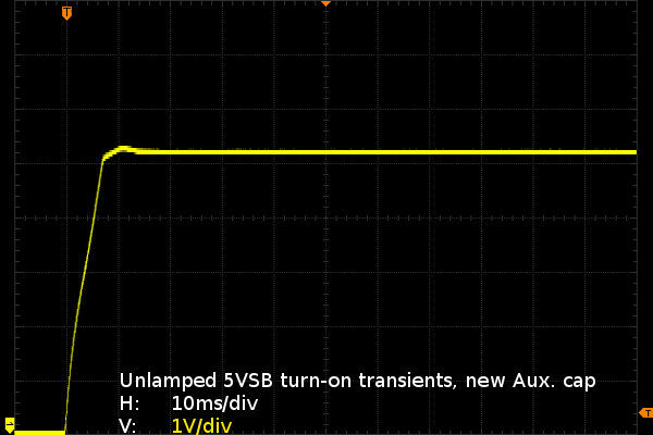
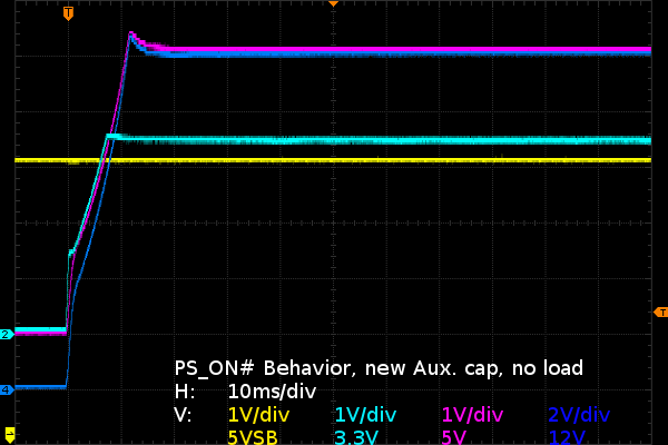
Look 'ma, no shunt regulator required anymore! The 8V power-up overshoot is gone, replaced by a far more reasonable 5.4V. That's within ATX's 10% turn-on transient specification. After that, the 5VSB output settles down to 5.2V on its own.
Get Tom's Hardware's best news and in-depth reviews, straight to your inbox.
The main outputs' ramp-up also looks as good as it is ever going to be. This is smelling like a definitive fix in the making. All the hissing during turn-on is gone as well.
Current page: Auxiliary Output Capacitor Replacement
Prev Page Auxiliary Output Replacement? Next Page PWM Bypass Capacitor Results-
Nuckles_56 An interesting read, it was interesting following the process you used to troubleshoot the problemReply -
Crashman I used to do this for a living :)Reply
Don't tell my boss, I've managed to convince him that I'm only an expert at running benchmarks and writing about the results :) -
epsiloneri Disclaimers won't help. The people who will likely hurt themselves trying this are the same who lack the reading comprehension and self awareness to understand those disclaimers are directed at them. I admire you courage in publishing this.Reply
-
beetlejuicegr the truth is the paper clip and multimeter is all i can go in to psus. after all i haven't studied electricity or circuits or whatever.Reply
However i do hate to throw stuff earlier than it should, like you. -
C12Friedman I like this article and I fully agree with the conclusion. I've repaired a few PSU's but, for the most part I scavenge them anymore since I can't put them in a new system (nor would I want to) IMO they aren't really worth anything other than for on a test bench.Reply -
Mr A Daniel, I know next to nothing about electronics, and yet I could not stop reading this article. Fascinating! Thanks very much!Reply -
Urzu1000 This was a great article! It was informative, as well as interesting. Personally, I've only had one PSU fail on me so far. My brother-in-law's self-built computer had a really low-end Thermaltake PSU. 800W Bronze, and oh man, did that thing go out in a blaze of glory. Very loud popping, and smoke, and funny smells. When I ripped it out of the computer, there were burns inside the case. Miraculously, the other components remained unharmed, so I slapped in a new PSU (750W Gold Seasonic) and fired it up.Reply
Still working good, but I get black soot on my hands every time I open up that case. It's a black case, so it's hard to clean it off properly. -
Interesting article. I would have simply replaced the entire unit. You saw how to fix the failure, but how many units were damaged that you didn't see? A ticking time bomb that will eventually send some spike to your much more valuable hardware than a 10 year old PSU. Wasteful, yes. I get it. I don't like to waste either. And if it's on marginal hardware, fine. But on primary systems I'm not willing to take the risk. I'd rather throw away a 200$ part that has a 0.05$ repair solution, than risk frying 800$+ hardware.Reply
-
kalmquist "Antec's manufacturer (Channelwell in this case) got the live and neutral wires backwards, which means that in the “off” position, the neutral line gets opened and everything on the primary side becomes live instead of neutral."Reply
That's really bad--I doubt it is even legal to sell a power supply wired like that. I've never bought a CWT (Channelwell) power supply, and based on this I wouldn't buy one, except perhaps for a high end model where you might gamble that the company would exercise a bit more care.