PSU Repair: A Case Study
When your PSU won't start, most enthusiasts don't go beyond a paperclip or multimeter check. Today, we'll do a comprehensive repair of Antec's old SL300.
PCB Analysis
Time to see if my initial suspicions were correct by examining the circuit board.
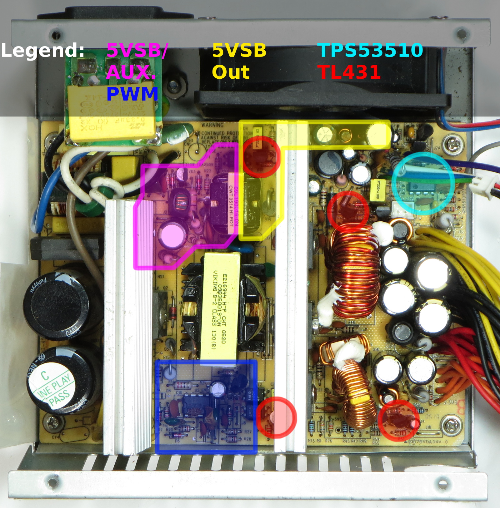
Before you ask, no, the components around the 5VSB feedback and main output pulse-width modulator chip are not burnt. The darkened area is just shadows. I took a few PCB shots during the repair, but none of them turned out good enough to use here due to perspective, framing, focus or other issues, so I had to re-open the supply once more to take this one.
The 5VSB output is provided by an all-discrete flyback circuit and a transformer with at least one auxiliary output based on the five wired pins on the transformer's primary side. The main chip of interest is the ST-branded switching IC that ends in “44B”. Its other markings appear to have been burnt off by the glue securing the nearby polyester caps. A quick online search for DIP-8 flyback regulators returns the UC3844B as the most likely match, though that remains to be confirmed by cross-checking the pin-out. Other integrated circuits of lesser interest, at least for this initial assessment, include a TI TPS3510 for power supervision (explaining the shutdowns roughly 80ms after outputs fail to ramp up), three Lite-On 817CN photocouplers and four Unisonic (UTC) TL431 programmable shunt voltage references.
At a glance, all capacitors that appear to be related to the feedback loop and switching circuit operation are either ceramic, polyester or other metal film for high stability and reliability, so the likelihood of a capacitor failure in those low-current circuits should be unlikely.
The TL431 chips (TO-92 packages) located directly next to photocouplers are obviously controlling their respective feedback couplers. The other two are not so obvious from the top but still guessable based on what else is nearby: the one located next to the orange wires is used to tie the ATX cable's 3.3V sense wire into the PWM feedback loop, while the other, located next to the fan header, manages fan speed with the help of two thermistors (one near the heat sink and the other at the main transformer).
Looking at the 5VSB's primary side area, it is almost entirely self-contained save for two traces sticking out of it: one to bring power from the top input filter cap in and the other connecting to the PWM controller area, presumably to power it up via an auxiliary output. This auxiliary output has a 47µF 25V capacitor on it, making it a potentially interesting target for analysis.
The middle of the primary side is used by the main MOSFET's (W12NK80) gate drive, snubber and current-sensing circuitry. If anything went wrong there, magic smoke would get released in no time flat, so there is nothing worth messing around with.
Get Tom's Hardware's best news and in-depth reviews, straight to your inbox.
Following traces and components starting from the main MOSFET back towards the pulse modulator reveals a match for the gate drive and current-sense pins. Doing the same from the bottom input filter cap through jumper wires also reveals a match for the GND pin. Tracing the path from the 5VSB's auxiliary output also confirms a match for the VCC pin, and that the PWM is powered entirely by the 5VSB's auxiliary output. Components attached to the remaining pins are consistent with feedback, compensation and timing functions. Short of reverse-engineering component values, UC3844B is an exact match. The 22µF 50V bypass capacitor across the PWM circuit's VCC and GND pins would be another point of interest.
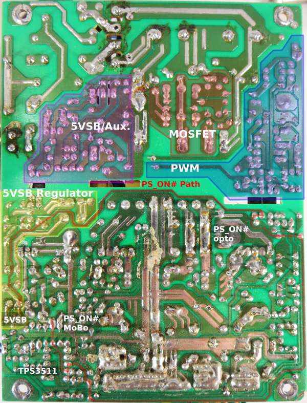
Have you ever wondered what sort of path the PS_ON signal takes from the ATX wire to control the main outputs? If the answer is yes, follow the red line. It starts with a thin trace breaking off from the 5VSB output, sneaking behind the main transformer output to reach the photocoupler that controls the main switcher's power, then creeping all the way around the board to reach the TI chip. That component is also powered from 5VSB. The trace goes around the PCB's entire secondary side.
-
Nuckles_56 An interesting read, it was interesting following the process you used to troubleshoot the problemReply -
Crashman I used to do this for a living :)Reply
Don't tell my boss, I've managed to convince him that I'm only an expert at running benchmarks and writing about the results :) -
epsiloneri Disclaimers won't help. The people who will likely hurt themselves trying this are the same who lack the reading comprehension and self awareness to understand those disclaimers are directed at them. I admire you courage in publishing this.Reply
-
beetlejuicegr the truth is the paper clip and multimeter is all i can go in to psus. after all i haven't studied electricity or circuits or whatever.Reply
However i do hate to throw stuff earlier than it should, like you. -
C12Friedman I like this article and I fully agree with the conclusion. I've repaired a few PSU's but, for the most part I scavenge them anymore since I can't put them in a new system (nor would I want to) IMO they aren't really worth anything other than for on a test bench.Reply -
Mr A Daniel, I know next to nothing about electronics, and yet I could not stop reading this article. Fascinating! Thanks very much!Reply -
Urzu1000 This was a great article! It was informative, as well as interesting. Personally, I've only had one PSU fail on me so far. My brother-in-law's self-built computer had a really low-end Thermaltake PSU. 800W Bronze, and oh man, did that thing go out in a blaze of glory. Very loud popping, and smoke, and funny smells. When I ripped it out of the computer, there were burns inside the case. Miraculously, the other components remained unharmed, so I slapped in a new PSU (750W Gold Seasonic) and fired it up.Reply
Still working good, but I get black soot on my hands every time I open up that case. It's a black case, so it's hard to clean it off properly. -
Interesting article. I would have simply replaced the entire unit. You saw how to fix the failure, but how many units were damaged that you didn't see? A ticking time bomb that will eventually send some spike to your much more valuable hardware than a 10 year old PSU. Wasteful, yes. I get it. I don't like to waste either. And if it's on marginal hardware, fine. But on primary systems I'm not willing to take the risk. I'd rather throw away a 200$ part that has a 0.05$ repair solution, than risk frying 800$+ hardware.Reply
-
kalmquist "Antec's manufacturer (Channelwell in this case) got the live and neutral wires backwards, which means that in the “off” position, the neutral line gets opened and everything on the primary side becomes live instead of neutral."Reply
That's really bad--I doubt it is even legal to sell a power supply wired like that. I've never bought a CWT (Channelwell) power supply, and based on this I wouldn't buy one, except perhaps for a high end model where you might gamble that the company would exercise a bit more care.

