PSU Repair: A Case Study
When your PSU won't start, most enthusiasts don't go beyond a paperclip or multimeter check. Today, we'll do a comprehensive repair of Antec's old SL300.
Preliminary Testing: The 5VSB Rail
All initial signs pointed towards the power supply's turn-on issues being related to 5VSB, so let's start investigating there.
Luckily for me, it turns out I still had what I believe to be the original caps in my junk box, so I was able to revisit the before and after effects of that 5VSB capacitor swap, seeing what I would have seen if I had an oscilloscope before my modifications.
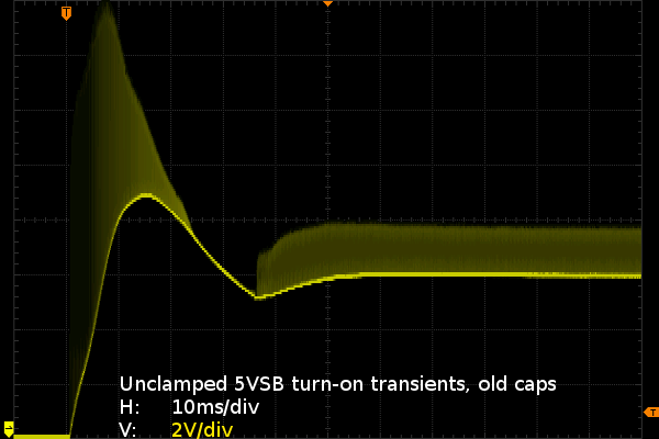
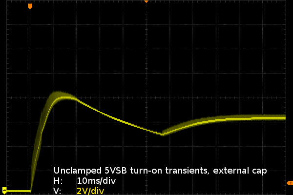
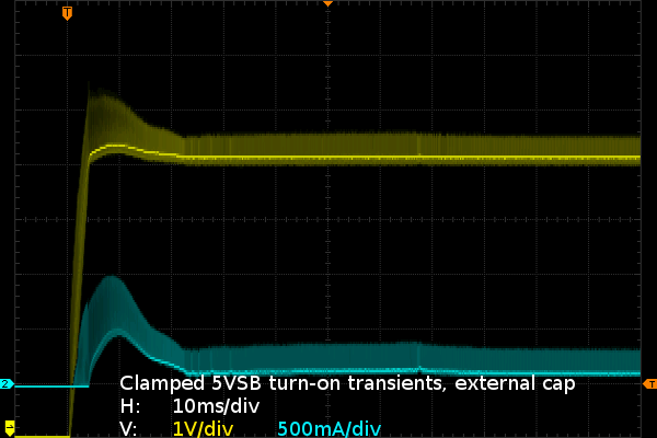
These screen captures show the 5VSB behavior upon throwing the hard-switch on. The first one is with the original 5VSB capacitors, and the second adds one of those 1200µF Panasonic FM caps I used in my LG repair plugged into the ATX connector. With only the old 680µF Fuhjyyu caps, the 5VSB output settles around 5V, is horribly noisy and shows horrible power-up transients peaking at up to 16V (clearly no good for capacitors rated only for 10V). With the external capacitor, voltage ends up settling around 6.4V, looks a whole lot cleaner but still overshoots to 8.5V. The original 5VSB capacitors are definitely busted if a capacitor connected at the end of the 30” ATX cable can provide this much of an improvement on ripples. The increased voltage from adding an external capacitor was unexpected.
While I was measuring voltage on 5VSB between hard-switch cycles under different loading conditions, I was surprised to see it settle anywhere from 5.4V to 6.4V depending on capacitive loading, power-on/off cycles, current draw and how long I let it warm up before turning it off and back on. This would seem to indicate a possible issue with the feedback loop, such as a flaky component or a cold solder joint. I have already ruled out cold solder joints by touching up the whole 5VSB section after the external cap failed to help, leaving flaky components as the prime suspect.
Before messing with anything more sensitive than output caps, let's see what else can be found first.
Rigging the Game
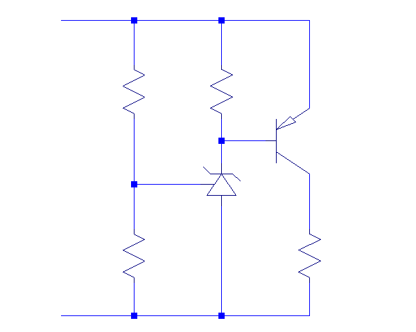
Since something related to 5VSB voltage appears to be causing issues, I decided to put together a shunt regulator based on a three-terminal reference and a booster transistor. Let the circuit figure out how much current it must draw to keep 5VSB at whatever voltage I want it at.
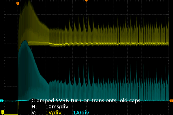
My simple shunt regulator is slower than I would have liked, with a reaction time of 4µs. Otherwise, it does exactly what I meant for it to do: draw however much current it needs to when 5VSB exceeds the set-point to drag it back down there. It would probably perform better if it was built on a PCB instead of a breadboard and connected directly to the supply PCB instead of 36” leads.
Get Tom's Hardware's best news and in-depth reviews, straight to your inbox.
The first slide shows how the 5VSB output reacts to having my 5.05V shunt regulator attached with the old caps. To prevent transients from rising to 16V as they did before, the shunt needs to draw about 4.2A and barely manages to keep them below 8V. With the external cap, transients peak at a still-unreasonable 6.4V and the shunt manages to keep them there by drawing less than 1A.
If I fail to fix the 5VSB stability issue at the source, I could put a 2A fuse in front of my shunt regulator and call that good enough for occasional bench use.
Current page: Preliminary Testing: The 5VSB Rail
Prev Page Background Story On Today's Patient Next Page Preliminary Testing: PS_ON# Behavior