The TFT Connection: Do NVIDIA and ATi Deliver?
DVI Compliance Tests, Continued
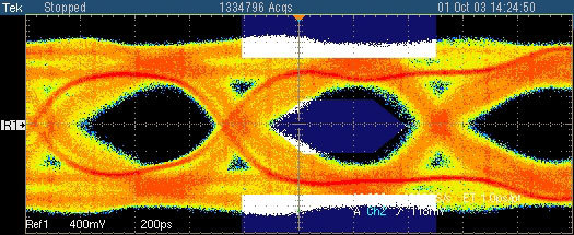
The greatest problems with serial high-speed communication are posed by jitter. Without jitter, you could always define and predict where and how signals are to be found. Most of the signal fluctuation is caused through the graphics chip's clock signal, resulting in "low frequency jitter" in a frequency range between 100 KHz and 10 MHz. In the eye diagram, signal fluctuations in frequency, data, data in relation to frequency, amplitude, and over- and undershoots can be made out as possible causes for jitter. Additionally, DVI measurements vary at the different frequencies that need to be taken into account for the eye diagram measurements. Using these tests, it is possible to judge the DVI quality of a device at a glance.
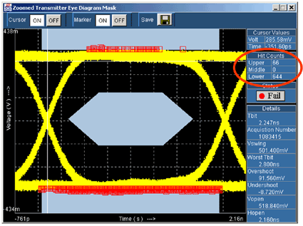
For the measurements, one million overlapping data points are collected using an oscilloscope. This is sufficient to judge the overall performance of a DVI link, since the signal does not change considerably over a longer period of time. Special software that Silicon Image has created in cooperation with Tektronix then creates a graphical representation of the data. The limits (blue areas), in which no signals should lie according to the DVI specification, are automatically added by the software. If data packets are within the blue areas, the test is considered failed and the device is not DVI compliant. The program immediately shows the results.
This graphics card does not pass the DCI Compliance test.
The software detects immediately whether or not a card passes.
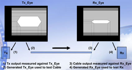
There are different compliant areas (eyes) defined for transmitter, cable and receiver. The signal must lie in that area to make the device DVI compliant.
Still, to understand exactly how DVI compliance is determined and what needs to be taken into account, we have to go into yet more detail.
Get Tom's Hardware's best news and in-depth reviews, straight to your inbox.
Current page: DVI Compliance Tests, Continued
Prev Page DVI Compliance Next Page DVI Jitter Management-
Thanks for this. Saved me lots of trouble with (not) chosing an incompatible DVI cable for my monitor / computer connection.Reply


