The TFT Connection: Do NVIDIA and ATi Deliver?
The TMDS Transmitter
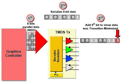
The TMDS (Transition Minimized Differential Signaling) transmitter sends the serial data through the cable in four different channels, one for the clock signal and one for each of the three colors. The eight bits of information for each color are transmitted as a serial 10 bit signal: eight bits for the color data, one bit to flag whether the signal transitions were minimized and one bit for DC balancing. The data itself is transmitted at 10 times the speed of the clock signal. This is achieved through a PLL chip, which acts as a frequency multiplier. This way, 1.65 GB/s of data are transmitted at a nominal frequency of 165 MHz.
A detailed look at the TMDS transmitter. The graphics chip relays the data to the transmitter as a 24 bit parallel signal (8 bits per color component). The transmitter converts the data into serial signals and adds two more bits. Since the data is transferred at 10 times the frequency of the signal, the frequency has to be multiplied using a PLL chip.
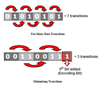
At first glance, encoding the signal in a Transition Minimized way may seem counterproductive, since an additional data bit has to be transferred without resulting in an increased overall bandwidth of the transmission. The point of the minimizing step, which uses an encoding algorithm working with the Boolean operations exclusive OR (XOR) or NOR (XNOR), lies in the safer transmission of data through the copper wiring of the cable. Every alternation in current from 0 to 1 (or vice versa) creates an electromagnetic emission (EMI). The transmission minimization reduces the number of such transitions, making the transmission less susceptible to interference from other electronic devices and creating fewer electromagnetic emissions of its own.
The upper picture shows the "worst case scenario of an 8-bit serial data stream (8 bit word): 7 transitions between 0 and 1. Below is the transition minimized version with the additional ninth encoding bit. The result: only three transitions.
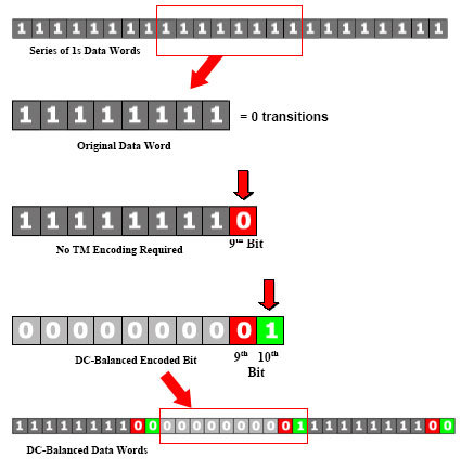
The tenth bit, which is used for DC-Balancing, also increases the transmission reliability. When a current is applied to a wire for a long period of time (relatively speaking, since we're talking about very high data rates here), it takes a while before the current drop off. This can lead to transmission problems, for example when only ones (data state 1 = current) are transmitted for a long period of time interrupted by a single zero(data state 0= no current). Depending on the quality of the copper cable, the 0 could be lost. The result would be an incorrectly rendered pixel. DC-Balancing is nothing but an inversion of the eight-bit data values in order to prevent overly long periods of identical data values being transmitted over the cable.
This example shows a series of eight-bit data words. (For the sake of simplicity, the ninth and 10th bits are omitted.) Below that, you see a single data word, first with the ninth bit (set to 0, since no TM encoding is required), then once again with the DC-bit set, leading to an inverted data word. The illustration shows how DC-balancing effectively prevents problems with charged cables.
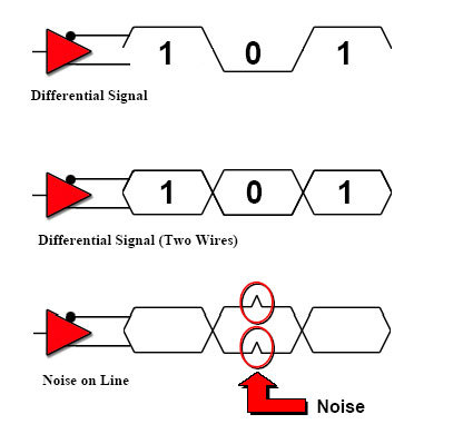
Obviously, great pains were taken to ensure signal integrity when the DVI 1.0 standard was drafted. Another technique employed to this end is what's called differential signaling. As we noted above, a normal digital transmission of serial data over a wire is easily susceptible to interference from external electronic impulses. For this reason, two wires are used for each DVI channel (red, green, blue and clock) and the second wire carries an inverted version of the original signal. The TMDS receiver (the monitor) then subtracts the two values from one another, allowing it to compensate for interference during transmission.
Get Tom's Hardware's best news and in-depth reviews, straight to your inbox.
The data for each channel is sent through two wires. One carries the original signal, the other an inverted version. The receiver then subtracts the difference. This way, signal interference can be compensated.
-
Thanks for this. Saved me lots of trouble with (not) chosing an incompatible DVI cable for my monitor / computer connection.Reply


