The TFT Connection: Do NVIDIA and ATi Deliver?
Digital Display Basics
Aside from the fact that TFT monitors require digital data to display an image, these new displays also differ from classical CRTs in several other very basic ways. For example, depending on its capabilities, an analog CRT monitor can display practically any resolution. The size of a pixel is not pre-determined on the monitors tube.
As a result of their working principle, TFTs, on the other hand, always have a fixed ideal (native) resolution. This is the only resolution at which the monitor will deliver optimal image quality. That limitation has nothing to do with DVI, however, but finds its root cause in the architecture of digital TFTs.
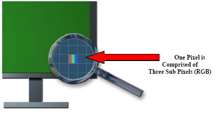
TFTs use a given matrix of very fine pixels. Each pixel consists of three diodes, one for each primary color (RGB: red, green, blue). A TFT screen with a native resolution of 1600x1200 (UXGA) comprises 1.92 million pixels!
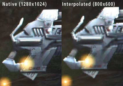
Naturally, TFT monitors can also display other resolutions as well. In these cases, the image will either be downscaled to size or interpolated. If, for example, a TFT possesses a native resolution of 1280x1024, the smaller resolution 800x600 will be scaled up to 1280x1024. Depending on the model, this will work well, more or less. The alternative is to display the image at 800x600, which reduces the size of the image on the screen and leaves a black frame around it.
Both snapshots show the image as seen on the TFT screen. The left one shows the image in the display's native resolution of 1280x1024 (Eizo L885). On the right you see the interpolated image at a resolution of 800x600. As a result of the enlargement of the pixels, the image becomes blocky. This kind of problem is unknown on CRT monitors.
A high transfer rate is required to allow a monitor to display an image at 1600x1200 (UXGA) with 1.92 million pixels at 60Hz. If you do the math, you will come to the conclusion that 115 MHz would be needed at this resolution. However, other factors such as "blanking time" also factor into the equation during transmission, increasing the required bandwidth.
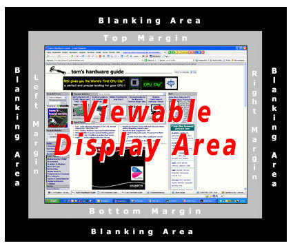
About 25% of all transmitted data is set aside for the blanking time. This is the time that is meant for repositioning of the electron cannon at the end of a line in CRT monitors (DVI is also designed for digital DVI monitors!). TFTs don't require the full blanking time, however!
Get Tom's Hardware's best news and in-depth reviews, straight to your inbox.
For every displayed picture (frame), a border area as well as the blanking area are transmitted along with the image itself. CRT monitors require the blanking area to give them time to shut off the electron cannon when it has finished drawing a line on the screen and to move the cannon to the next line, get it in position and then switch it back on to continue drawing there. The same happens once again at the end of the image, i.e. the bottom right-hand corner - the electron beam has to be switched off and repositioned at the top left corner of the screen.
Roughly 25% of the entire pixel data is taken up by the blanking time. Since TFT monitors don't use an electron cannon, ordering the diodes to glow directly, the greater part of the blanking time is a total waste. It was only implemented in DVI 1.0 because this standard was designed with both TFTs and digital CRTs (with a DAC in the monitor) in mind.


