PSUs 101: A Detailed Look Into Power Supplies
The objective of this article is to provide detailed information about the most crucial part of a personal computer (PC) system, its power supply unit. Follow us on this journey into PSU territory and we promise that you will gain valuable knowledge.
Bridge Rectifiers And APFC
Bridge Rectifiers
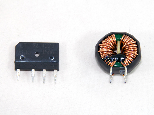
One or more bridge rectifiers fully rectify the AC power stream after it passes the EMI/transient filter. During this process, AC is converted to DC with increased voltage level (if we have 230V input, then the DC output of the bridge rectifier will be √2x230=325.27VDC). Afterward, the DC signal is fed to the FET(s) of the APFC stage.
Active Power Factor Correction Converter (APFC)
Before we talk about the APFC stage, let's go over some basic concepts. Power factor is defined as the ratio of real power to apparent power (kW/kVA), and power is the product of voltage and current (P = V x I).
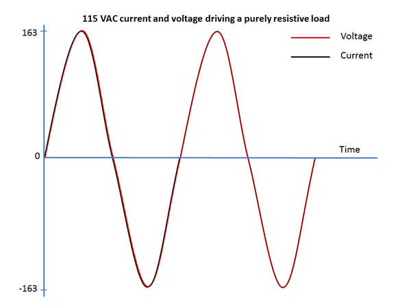
We have two basic types of loads: resistive (the load consists only of resistors) and reactive (the load consists of inductors, capacitors or both). In a reference system with a linear load that is fed with AC power, both current and voltage curves are sinusoidal (the sine wave or sinusoid is a mathematical function that describes a smooth, repetitive oscillation). If the load is purely resistive, then the two above quantities reverse their polarity at the same time (the phase angle between voltage and current is 0 degrees), so at every instant, the product of voltage and current is positive. That means the direction of energy flow does not reverse, so only real power is transferred to the load.
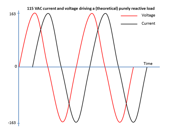
In cases where the load is purely reactive, there is a time shift (the maximum is theoretically 90 degrees, but is typically 45 degrees) between voltage and current, so the product of these two for half of each cycle is positive, and for the other half, it is negative (when the voltage is at its peak, either positive or negative, current is zero and vice-versa). Thus, on average, as much energy flows to the load as flows back to the source (power grid). If we analyze a whole cycle, then we will see that there is no net energy flow and that only reactive energy flows, as there is no net transfer of energy toward the load.
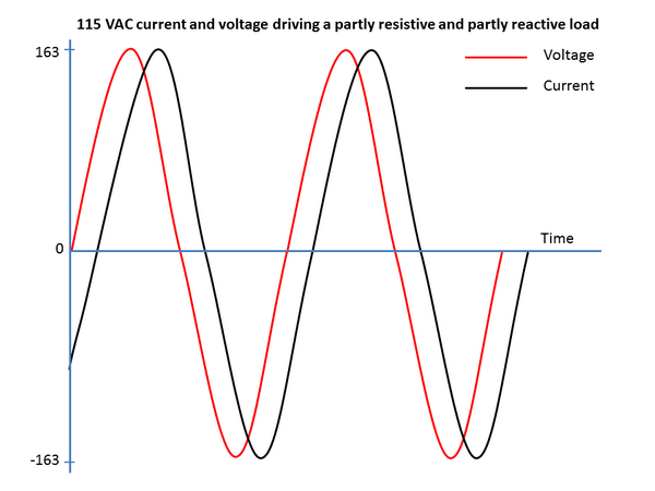
However, the above explanation is only theoretical because, in real life, all loads (or circuits) present resistance, inductance and capacitance. So, both real and reactive power will flow to them. Apparent power is the vector sum of real and reactive power, or the product of the root-mean-square of voltage and current. As mentioned, power factor is the ratio between real and apparent power. We must also stress that residential consumers pay only for the real power (watts) that they consume, and not for apparent power. On the contrary, business consumers have to pay for apparent power as well.
Although residential consumers do not have to pay for apparent power, in order to minimize apparent power usage, the EU standard EN61000-3-2 states that all switched mode power supplies with output power of more than 75W must include a passive PFC converter. In addition, the 80 PLUS certification requires a power factor of 0.9 or more. Some years ago, many PSU manufacturers used passive PFC (PPFC) in their products. The PPFC uses a filter that passes current only at line frequency, 50 or 60Hz, so the harmonic current is reduced and the nonlinear load is transformed to a linear load. Then, with the usage of capacitors or inductors, the power factor can be brought close to unity. The disadvantage of PPFC is that it attains smaller power factors than APFC and requires a voltage doubler for the PSU to be compatible with 115/230V. On the contrary, PPFC has higher efficiency than APFC.
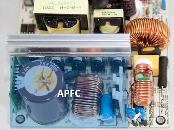
An APFC is basically an AC/DC converter that controls the current supplied to the PSU via pulse-width modulation (PWM). Initially, the bridge rectifier rectifies the AC voltage, and then the PWM triggers the APFC FETs (usually two of them), which separate the intermediate DC voltage into constant pulse sequences. These pulses are smoothed out by the bulk capacitor(s) and are fed to the main switchers. Right before the smoothing capacitor(s), we always find an inductor (coil) that has the ability to limit the sudden rise of current without dissipating energy, since it's a reactive component. This coil is necessary because all capacitors connected directly to a DC signal show uncontrolled inrush current, and this inductor limits it effectively. The aforementioned inductor can also play the role of a current transformer, informing the APFC's controller about the current that passes through the circuit. Finally, in most cases, there is also a thermistor in the APFC to further limit the inrush current, especially in the switch-on phase of the PSU, where the smoothing capacitor is fully uncharged.
Get Tom's Hardware's best news and in-depth reviews, straight to your inbox.
In APFC, two different types of control are used: discontinuous conduction mode (DCM), where the PFC FETs are turned on only when the inductor current has reached zero, and continuous conduction mode (CCM), where the FETs are turned on when the inductor current is still above zero and thus all reverse recovery energy is dissipated in the FETs. In the APFC stage of PSUs, the second mode (CCM) is mostly used. It is ideal for output power over 200W because it offers the lowest peak-to-average-current ratio for the converter. The main drawbacks of CCM are the loss and EMI generation associated with turning off the boost diode. The reverse recovery currents of the diode cause significant power dissipation to the FETs and increased EMI. That's why we usually see an X capacitor after the bridge rectifier.
Current page: Bridge Rectifiers And APFC
Prev Page EMI/Transient Filtering Stage Next Page Main Switchers And Transformers
Aris Mpitziopoulos is a contributing editor at Tom's Hardware, covering PSUs.
-
Alexis Shaw In your list of top-tier capacitor manufacturers you missed out on some of the better american and european manufacturers, while these may not be used on many consumer-grade power supplies they are definitely top-tier and if you were to find them you would be happy. I suggest the addition of at least:Reply
Cornell Dubilier (USA)
Illinois Capacitor (Now owned my Cornell Dubilier)
Kemet Corporation (USA)
ELNA (Japan)
EPCOS (TDK company) (Germany)
Vishay (USA)
Würth Elektronik (Germany)
-
Aris_Mp Thank you very much for the list you provided. I am aware of almost all cap brands that you mentioned but unfortunately so far I found none of them inside a desktop/consumer grade PSU. I will think about it however (and also make a research on these cap brands), if I should include them as well inside my list.Reply
-
InvalidError Reply
There is a very high probability you have seen PSUs with several Kemet capacitors in them. You never noticed them simply because SMD capacitors are too small to carry logos, brand name or even value designations.16585466 said:Thank you very much for the list you provided. I am aware of almost all cap brands that you mentioned but unfortunately so far I found none of them inside a desktop/consumer grade PSU.
The other brands are mostly found in specialty applications such as lab instruments, industrial machines and high-end audio. -
Math Geek very interesting read. more in depth than i need to know yet for the most part understandable and with careful reading it did not leave me confused.Reply
nice article. -
TallestJon96 I only read 2/3 of it, but it's a good article.Reply
I basically have committed PC heresy with my cx600m. However I think that I'm in the clear with my 65w CPU and 145w CPU. I'd bet my total power draw is actually below 300w, the supposed highest efficiency point of a PSU.
As a gamer, not a professional, I think it is better to get low power parts, and get a higher rating than you need, rather than get high power parts and high quality PSUs.
Additionally, if you compare power consumption of a typical system from today to one from 5 years ago, power draw is considerably lower, with the exception of certain graphics cards. *cough* 390x *cough* -
powernod I decided to sign up at Tom's forum, and the only reason was to state how excellent is Aris's article!!!Reply
Thanks Aris for this very useful article on behalf of us all who want to learn the basic knowledge for PSUs.
Haven't finished it yet, but i'm very anxious for it !!! -
traumadisaster I'm glad there are people dedicated to this but I'm not. I can't even read all of the chapter titles in this article. I disagree with the importance you place on this and all of the references you made to this being crucial knowledge.Reply
PSU and MB are insignificant to me and I can blindly pick one by reviewing user comments from newegg in about 5 min, and it will last for years. For less than $100 each I'm set for nearly a decade.
CPU and gfx card now that affects fps and is over $1000, actually the most important part to me. -
Alexis Shaw Reply16589602 said:I'm glad there are people dedicated to this but I'm not. I can't even read all of the chapter titles in this article. I disagree with the importance you place on this and all of the references you made to this being crucial knowledge.
PSU and MB are insignificant to me and I can blindly pick one by reviewing user comments from newegg in about 5 min, and it will last for years. For less than $100 each I'm set for nearly a decade.
CPU and gfx card now that affects fps and is over $1000, actually the most important part to me.
I heartily dissagree, user are not the best way to judge reliability, and a bad powersupply is at fult most of the time there is a hardware issue. Further a power supply should last more than one system build, and in general I keep mine for a decade at a time at least. So an investment in a good power supply is not a waste, and a bad one will kill that precious $1000 GPU or CPU. The demo dart power supply on the motherboard is a similar story, however in general they are of higher quality than a cheap mains supply.
-
Alexis Shaw Reply16585679 said:
There is a very high probability you have seen PSUs with several Kemet capacitors in them. You never noticed them simply because SMD capacitors are too small to carry logos, brand name or even value designations.16585466 said:Thank you very much for the list you provided. I am aware of almost all cap brands that you mentioned but unfortunately so far I found none of them inside a desktop/consumer grade PSU.
The other brands are mostly found in specialty applications such as lab instruments, industrial machines and high-end audio.
As well as SMT ceramic capacitors, Kemet makes through hole aluminium electrolytic capacitors. These are of high quality, though not as well known as their SMT capacitors. They also make high quality polymer SMT capacitors that are used as bulk capacitors on the power distribution circuitry on laptops and other devices.
