PSUs 101: A Detailed Look Into Power Supplies
The objective of this article is to provide detailed information about the most crucial part of a personal computer (PC) system, its power supply unit. Follow us on this journey into PSU territory and we promise that you will gain valuable knowledge.
Resistors, Transistors And Diodes
Resistors
Resistors are the most commonly used electronic component. Their role is to simply restrict the flow of electrical current when necessary and make sure that the correct voltage is supplied to a component. We measure resistance in ohms. However, since an ohm represents a very small resistance, in most cases you will see resistance measured in kΩ (1000Ω) or MΩ (1,000,000Ω).
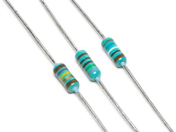
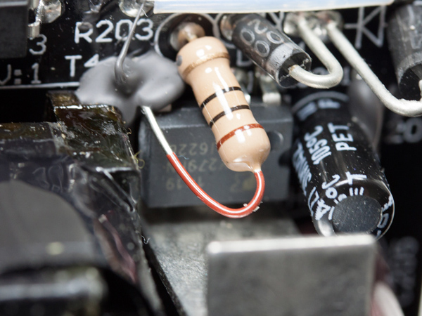
When we combine several resistors in a series, then we simply add their resistance (equation 1 below). The same current flows through all resistors connected in series, but there is some voltage drop at each resistor.
(1) Rseries = R1+R2+R3…
When we combine several resistors in parallel, then we decrease the overall resistance (equation 2). In addition, when there are multiple resistance branches in a circuit the current flowing into each of them is inversely proportional to the resistance of the branch.
(2) Rparallel = 1/(1/R1+1/R2+1/R3…)
Since we made it this far, we should mention Ohm's law: Voltage equals current multiplied by resistance (equation 3). Another equally famous law is Joule's law (equation 4), which gives the relation of power (P) with voltage (V) and current (I).
(3) V = I x R
Get Tom's Hardware's best news and in-depth reviews, straight to your inbox.
(4) P = V x I = (I x R) x I = I2 X R
Transistors
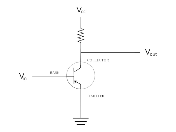
The transistor is considered to be the biggest discovery, or innovation, of the 20th century. Indeed, inside every electronics device nowadays you will find transistors working effortlessly and reliably. The two most common types of transistors are bipolar junction transistors (BJTs), which can be broken down into NPN and PNP transistors, and field effect transistors (FETs). Similar to BJTs, FETs come in N-channel and P-channel types. The two major types of FETs are MOSFETs (Metal-Oxide Semiconductor FETs) and JFETs (Junction FETs).
A transistor has three leads: source, gate and drain. To explain its operation, we will use a simple paradigm. Think of a pipe that connects a source of water to a drain. The valve (gate) controls the flow of water either by being fully closed, partially open or fully open. The same is true in a transistor. By applying voltage or current (depending on the transistor type) to the gate, we can control the current flowing from source to drain. In NPN transistors the source, gate and drain are called collector, base and emitter, respectively. The two main roles of transistors are amplifying small signals and switching.
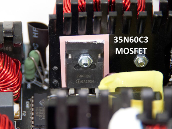
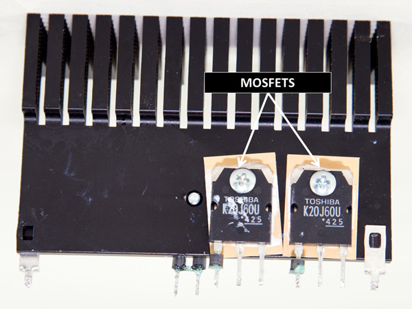
In PSUs, mostly NPN FETs are used in the APFC converter and as main switchers. In order to further increase efficiency, they are also used in the secondary side to rectify the DC outputs (synchronous design).
Diodes
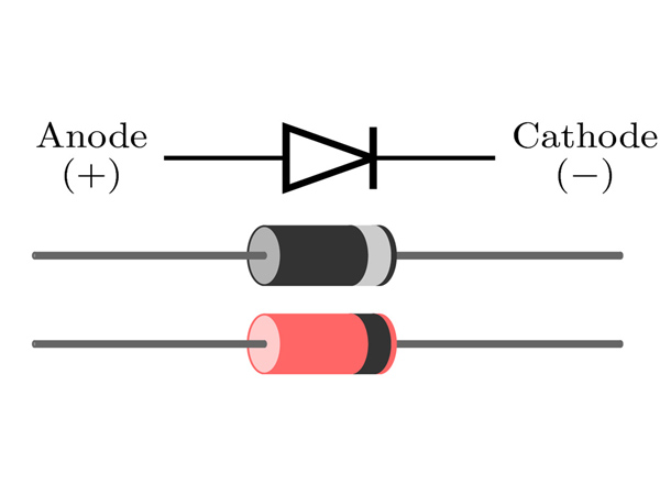
A diode can be considered as a one-way valve. When voltage is applied to it, it allows current to flow in one direction but not through the other. The process is sometimes also called the rectifying process. The one end of a diode is called an anode and the other a cathode. Most of the diodes allow current to freely flow from anode to cathode. When current starts to flow from a diode, there is a constant voltage drop on it. For most diodes this voltage drop is approximately 0.7V.
All diodes have a current rating that states the maximum forward current they can withstand. Also, the Peak Inverse Voltage (PIV) rating depicts the maximum reverse voltage that a diode can handle before it breaks down. Now, if you want to find out if a diode is working properly, then all you have to do is measure it with a multimeter, using the ohms scale. In one direction the diode should have low resistance (forward-biased), and in the opposite direction you will see high resistance (reverse-biased).
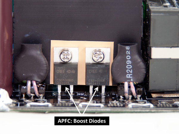
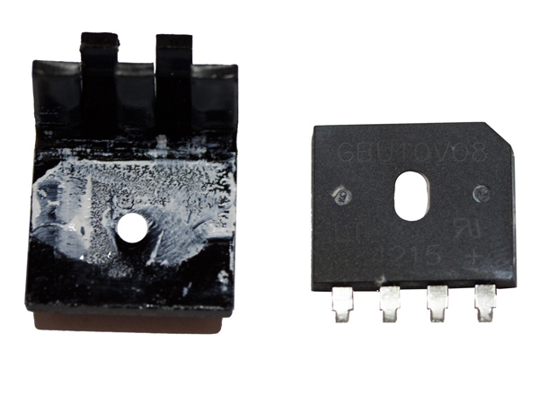
Diodes have numerous uses. Some of the most common are voltage regulation, AC rectifying (bridge rectifiers), LED applications, overvoltage protection and more. In many PSUs, besides the common diodes, we almost always find bridge rectifiers (four diodes in a bridge arrangement that provides full-wave rectification to incoming AC signal) and Schottky Barrier Diodes (SBRs). The SBRs are used in the APFC section (boost diodes) and sometimes for the rectifying process of the DC outputs in the secondary side. Schottky diodes are special diodes with a lower forward voltage drop than the common diodes. However, in high-efficiency PSUs they are fully replaced by FETs that dissipate less energy. But there are also cases where SBRs work along with a FET replacing its internal diode, providing increased efficiency since the actual regulation is still handled by the FET.
Current page: Resistors, Transistors And Diodes
Prev Page Capacitors Manufacturer Tier List Next Page SMPS Vs. Linear Regulators
Aris Mpitziopoulos is a contributing editor at Tom's Hardware, covering PSUs.
-
Alexis Shaw In your list of top-tier capacitor manufacturers you missed out on some of the better american and european manufacturers, while these may not be used on many consumer-grade power supplies they are definitely top-tier and if you were to find them you would be happy. I suggest the addition of at least:Reply
Cornell Dubilier (USA)
Illinois Capacitor (Now owned my Cornell Dubilier)
Kemet Corporation (USA)
ELNA (Japan)
EPCOS (TDK company) (Germany)
Vishay (USA)
Würth Elektronik (Germany)
-
Aris_Mp Thank you very much for the list you provided. I am aware of almost all cap brands that you mentioned but unfortunately so far I found none of them inside a desktop/consumer grade PSU. I will think about it however (and also make a research on these cap brands), if I should include them as well inside my list.Reply
-
InvalidError Reply
There is a very high probability you have seen PSUs with several Kemet capacitors in them. You never noticed them simply because SMD capacitors are too small to carry logos, brand name or even value designations.16585466 said:Thank you very much for the list you provided. I am aware of almost all cap brands that you mentioned but unfortunately so far I found none of them inside a desktop/consumer grade PSU.
The other brands are mostly found in specialty applications such as lab instruments, industrial machines and high-end audio. -
Math Geek very interesting read. more in depth than i need to know yet for the most part understandable and with careful reading it did not leave me confused.Reply
nice article. -
TallestJon96 I only read 2/3 of it, but it's a good article.Reply
I basically have committed PC heresy with my cx600m. However I think that I'm in the clear with my 65w CPU and 145w CPU. I'd bet my total power draw is actually below 300w, the supposed highest efficiency point of a PSU.
As a gamer, not a professional, I think it is better to get low power parts, and get a higher rating than you need, rather than get high power parts and high quality PSUs.
Additionally, if you compare power consumption of a typical system from today to one from 5 years ago, power draw is considerably lower, with the exception of certain graphics cards. *cough* 390x *cough* -
powernod I decided to sign up at Tom's forum, and the only reason was to state how excellent is Aris's article!!!Reply
Thanks Aris for this very useful article on behalf of us all who want to learn the basic knowledge for PSUs.
Haven't finished it yet, but i'm very anxious for it !!! -
traumadisaster I'm glad there are people dedicated to this but I'm not. I can't even read all of the chapter titles in this article. I disagree with the importance you place on this and all of the references you made to this being crucial knowledge.Reply
PSU and MB are insignificant to me and I can blindly pick one by reviewing user comments from newegg in about 5 min, and it will last for years. For less than $100 each I'm set for nearly a decade.
CPU and gfx card now that affects fps and is over $1000, actually the most important part to me. -
Alexis Shaw Reply16589602 said:I'm glad there are people dedicated to this but I'm not. I can't even read all of the chapter titles in this article. I disagree with the importance you place on this and all of the references you made to this being crucial knowledge.
PSU and MB are insignificant to me and I can blindly pick one by reviewing user comments from newegg in about 5 min, and it will last for years. For less than $100 each I'm set for nearly a decade.
CPU and gfx card now that affects fps and is over $1000, actually the most important part to me.
I heartily dissagree, user are not the best way to judge reliability, and a bad powersupply is at fult most of the time there is a hardware issue. Further a power supply should last more than one system build, and in general I keep mine for a decade at a time at least. So an investment in a good power supply is not a waste, and a bad one will kill that precious $1000 GPU or CPU. The demo dart power supply on the motherboard is a similar story, however in general they are of higher quality than a cheap mains supply.
-
Alexis Shaw Reply16585679 said:
There is a very high probability you have seen PSUs with several Kemet capacitors in them. You never noticed them simply because SMD capacitors are too small to carry logos, brand name or even value designations.16585466 said:Thank you very much for the list you provided. I am aware of almost all cap brands that you mentioned but unfortunately so far I found none of them inside a desktop/consumer grade PSU.
The other brands are mostly found in specialty applications such as lab instruments, industrial machines and high-end audio.
As well as SMT ceramic capacitors, Kemet makes through hole aluminium electrolytic capacitors. These are of high quality, though not as well known as their SMT capacitors. They also make high quality polymer SMT capacitors that are used as bulk capacitors on the power distribution circuitry on laptops and other devices.
