PSUs 101: A Detailed Look Into Power Supplies
The objective of this article is to provide detailed information about the most crucial part of a personal computer (PC) system, its power supply unit. Follow us on this journey into PSU territory and we promise that you will gain valuable knowledge.
Main Switchers And Transformers
The main switchers operate in two modes only: on (fully conductive) and off (fully non-conductive). They chop the DC signal coming from the smoothing capacitor into pulses, whose amplitude is the magnitude of the input voltage, while the duty cycle is controlled by a switching regulator controller. Thus, the DC signal is converted to an AC rectangular waveform that is fed to the transformer.
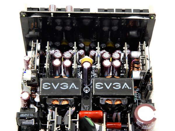
The transformer steps down the voltage feeding the secondary rectifiers that generate all DC outputs (+12V, 5V, 3.3V, 5VSB, minus 12V). The transformer also acts as an isolator between the primary side and the secondary side. In some larger-capacity PSUs, there are two main transformers, instead of one, installed in parallel, simply because a single transformer would have very large dimensions and thus wouldn't fit inside the PSU's casing.
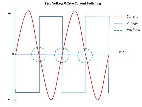
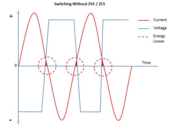
When the switchers are in the "on" state, there is zero voltage running across them (theoretically), and when they are in the "off" state, there is zero current running through them. Therefore, V x I = 0. This means there is no power loss on the main switching FETs.
However, this represents an ideal situation. In real life, there are power losses, as no transistor/FET can switch instantly. There is always a small period when a transistor (switch) is between the "on" and "off" states and VxI does not equal zero. That's why all FETs in a PSU are cooled down by heat sinks and, in most cases, by a fan (because there are also passively-cooled PSUs).


Get Tom's Hardware's best news and in-depth reviews, straight to your inbox.
Current page: Main Switchers And Transformers
Prev Page Bridge Rectifiers And APFC Next Page Output Rectifiers And Filters
Aris Mpitziopoulos is a contributing editor at Tom's Hardware, covering PSUs.
-
Alexis Shaw In your list of top-tier capacitor manufacturers you missed out on some of the better american and european manufacturers, while these may not be used on many consumer-grade power supplies they are definitely top-tier and if you were to find them you would be happy. I suggest the addition of at least:Reply
Cornell Dubilier (USA)
Illinois Capacitor (Now owned my Cornell Dubilier)
Kemet Corporation (USA)
ELNA (Japan)
EPCOS (TDK company) (Germany)
Vishay (USA)
Würth Elektronik (Germany)
-
Aris_Mp Thank you very much for the list you provided. I am aware of almost all cap brands that you mentioned but unfortunately so far I found none of them inside a desktop/consumer grade PSU. I will think about it however (and also make a research on these cap brands), if I should include them as well inside my list.Reply
-
InvalidError Reply
There is a very high probability you have seen PSUs with several Kemet capacitors in them. You never noticed them simply because SMD capacitors are too small to carry logos, brand name or even value designations.16585466 said:Thank you very much for the list you provided. I am aware of almost all cap brands that you mentioned but unfortunately so far I found none of them inside a desktop/consumer grade PSU.
The other brands are mostly found in specialty applications such as lab instruments, industrial machines and high-end audio. -
Math Geek very interesting read. more in depth than i need to know yet for the most part understandable and with careful reading it did not leave me confused.Reply
nice article. -
TallestJon96 I only read 2/3 of it, but it's a good article.Reply
I basically have committed PC heresy with my cx600m. However I think that I'm in the clear with my 65w CPU and 145w CPU. I'd bet my total power draw is actually below 300w, the supposed highest efficiency point of a PSU.
As a gamer, not a professional, I think it is better to get low power parts, and get a higher rating than you need, rather than get high power parts and high quality PSUs.
Additionally, if you compare power consumption of a typical system from today to one from 5 years ago, power draw is considerably lower, with the exception of certain graphics cards. *cough* 390x *cough* -
powernod I decided to sign up at Tom's forum, and the only reason was to state how excellent is Aris's article!!!Reply
Thanks Aris for this very useful article on behalf of us all who want to learn the basic knowledge for PSUs.
Haven't finished it yet, but i'm very anxious for it !!! -
traumadisaster I'm glad there are people dedicated to this but I'm not. I can't even read all of the chapter titles in this article. I disagree with the importance you place on this and all of the references you made to this being crucial knowledge.Reply
PSU and MB are insignificant to me and I can blindly pick one by reviewing user comments from newegg in about 5 min, and it will last for years. For less than $100 each I'm set for nearly a decade.
CPU and gfx card now that affects fps and is over $1000, actually the most important part to me. -
Alexis Shaw Reply16589602 said:I'm glad there are people dedicated to this but I'm not. I can't even read all of the chapter titles in this article. I disagree with the importance you place on this and all of the references you made to this being crucial knowledge.
PSU and MB are insignificant to me and I can blindly pick one by reviewing user comments from newegg in about 5 min, and it will last for years. For less than $100 each I'm set for nearly a decade.
CPU and gfx card now that affects fps and is over $1000, actually the most important part to me.
I heartily dissagree, user are not the best way to judge reliability, and a bad powersupply is at fult most of the time there is a hardware issue. Further a power supply should last more than one system build, and in general I keep mine for a decade at a time at least. So an investment in a good power supply is not a waste, and a bad one will kill that precious $1000 GPU or CPU. The demo dart power supply on the motherboard is a similar story, however in general they are of higher quality than a cheap mains supply.
-
Alexis Shaw Reply16585679 said:
There is a very high probability you have seen PSUs with several Kemet capacitors in them. You never noticed them simply because SMD capacitors are too small to carry logos, brand name or even value designations.16585466 said:Thank you very much for the list you provided. I am aware of almost all cap brands that you mentioned but unfortunately so far I found none of them inside a desktop/consumer grade PSU.
The other brands are mostly found in specialty applications such as lab instruments, industrial machines and high-end audio.
As well as SMT ceramic capacitors, Kemet makes through hole aluminium electrolytic capacitors. These are of high quality, though not as well known as their SMT capacitors. They also make high quality polymer SMT capacitors that are used as bulk capacitors on the power distribution circuitry on laptops and other devices.
