ASRock's $40 16-pin power cable has overheating protection designed to prevent meltdowns — company claims a 90-degree design ensures worry-free installation
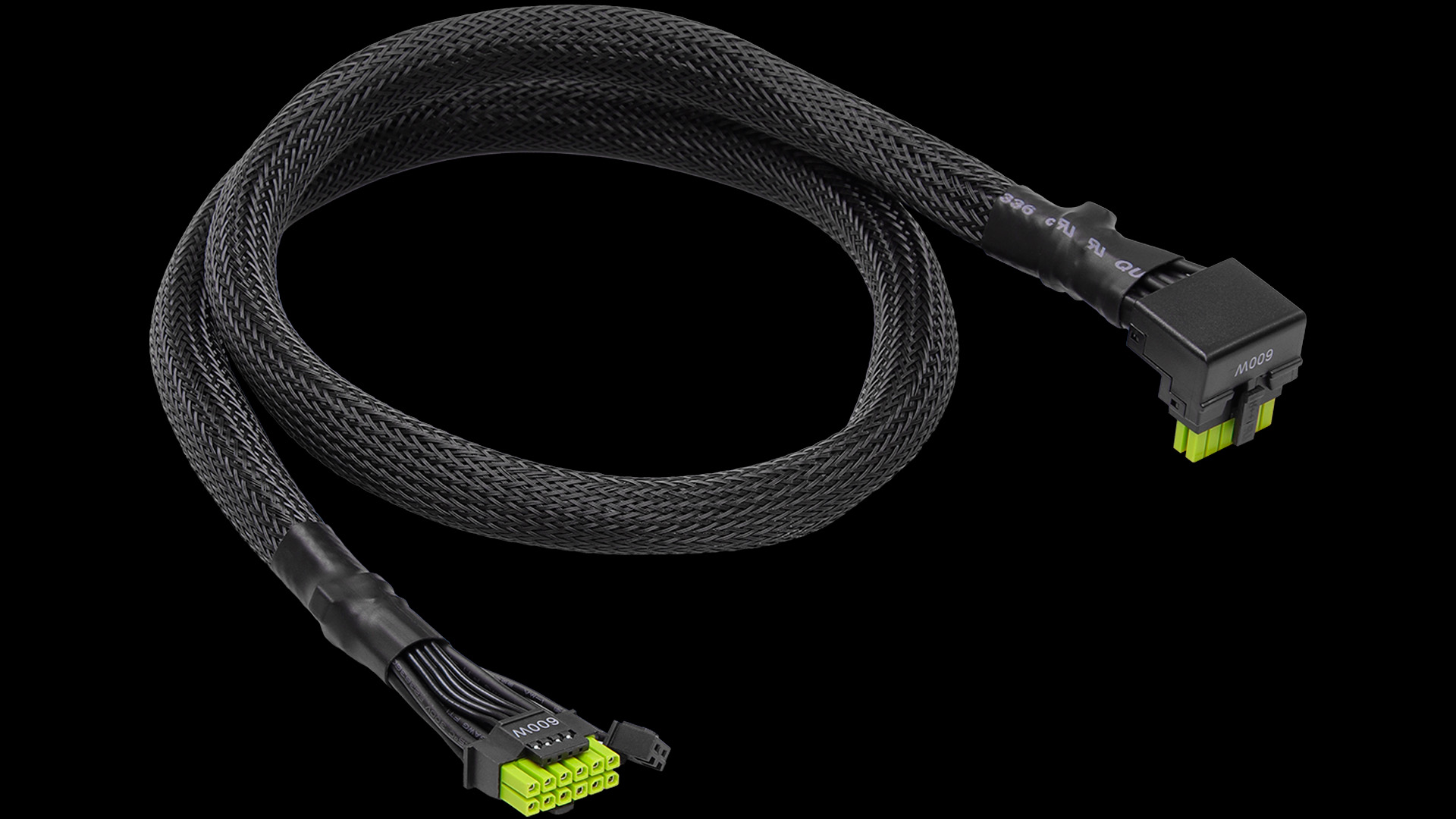
The 16-pin (12VHPWR) power connector melting on some of the best graphics cards has caused headaches for consumers and graphics card vendors. The latter have resorted to adding extra mechanisms to their products for protection, such as ASRock's latest 12V-2x6 power cable (CB-12V2X6L600W), which features overheating protection.
The ASRock 12V-2x6 power cable, rated for 105 degrees Celsius, aims to attack the 16-pin power connector meltdowns from all angles. What really sets the ASRock 12V-2x6 power cable apart from the competition is the overheating protection. The company has implemented a tiny NTC (Negative Temperature Coefficient) sensor on the power connector that goes to the graphics card. It essentially monitors the temperature and sends the signal to the power supply.
While the ASRock 12V-2x6 power cable is compliant with both ATX 3.1 and PCIe 5.1 standards, it's only compatible with ASRock's Taichi or Phantom Gaming power supplies. This makes sense because not all power supplies have the same features as ASRock's offering. The only requirement is that the power supply must have a minimum capacity of 750W. The 600W-rated cable, which is 27.6 inches (700 mm) long, utilizes 16 AWG wires and HCS (High-Current System) terminals, which are plastic compliant with the 94V-0 certification.
If you've never heard of the UL 94 standard, it's essentially a plastics flammability criterion established by Underwriters Laboratories (UL). The organization develops standards based on how plastics react to flames, such as the time it takes to ignite or extinguish. The V-0 rating is basically the highest level of resistance when it comes to vertical burning. It means that the burning stops within 10 seconds on the vertical part with drops of plastic that do not cause inflammation. In other words, if the power connector on the ASRock 12V-2x6 power cable catches fire, it won't consistently burn until only ash is left.
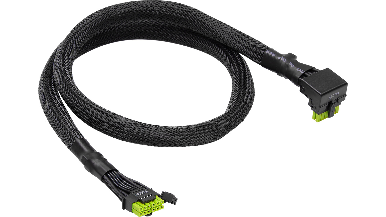
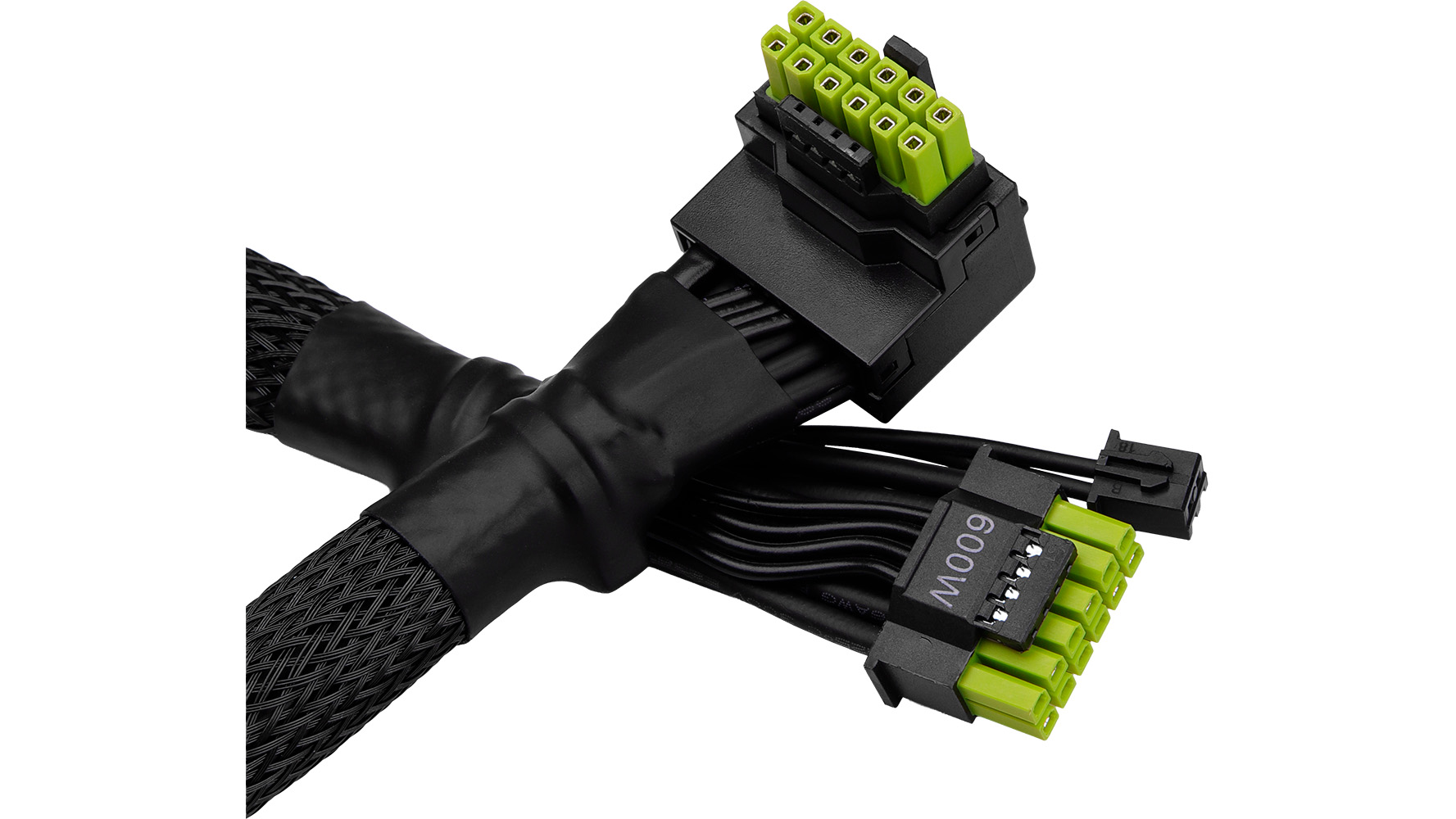
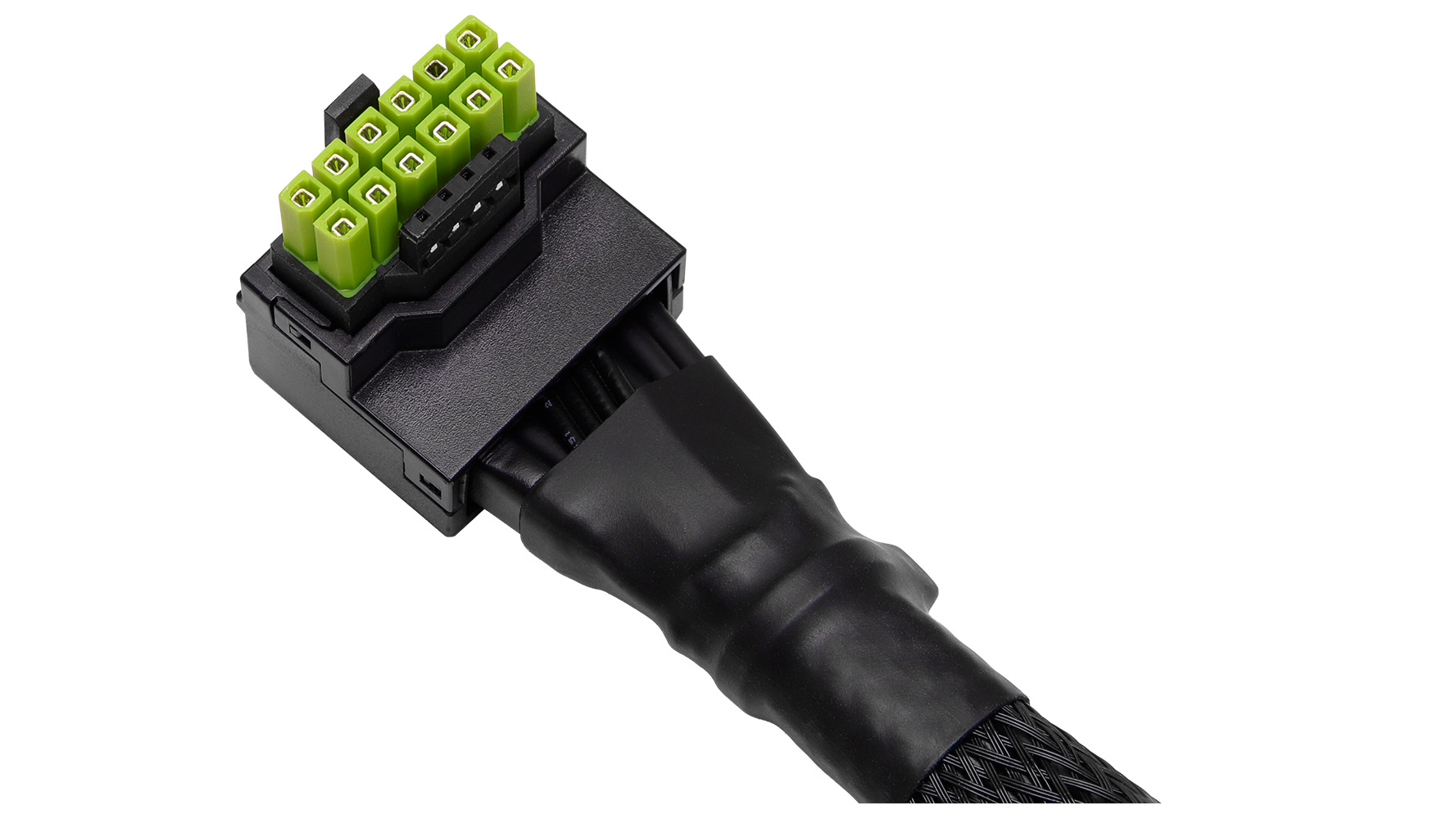
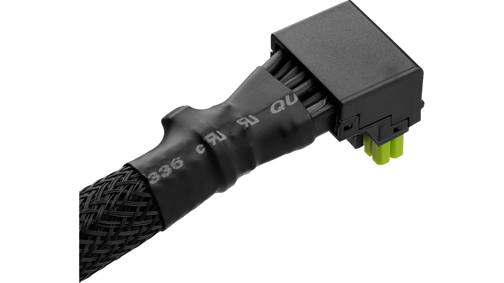
The ASRock 12V-2x6 power cable also addresses past issues with the problematic 16-pin power connector. For example, it has a 90-degree connector on the graphics card side. The design ensures that you don't have to worry about bending the power cable at a specific radius or distance. Furthermore, it also facilitates easier cable management.
You may also notice that the power connectors on the 12V-2x6 power cable are colored in bright green. The color choice extends far beyond aesthetic purposes. The colored power connectors indicate whether you've correctly connected them to your power supply and graphics card. Many graphics card and power supply manufacturers, such as MSI, have adopted this simple countermeasure to prevent user error. However, we've seen that it's not fail-proof, as there have been reports of colored connectors still melting.
As a bonus, ASRock includes four different stickers that you can place on the 12V-2x6 power connector, which connects to the graphics card. These stickers correspond to the company's ASRock, Taichi, Phantom Gaming, and Steel Legend branding.
Get Tom's Hardware's best news and in-depth reviews, straight to your inbox.
You can buy the ASRock 12V-2x6 power cable on Newegg for $39.99. If you own a compatible power supply and a graphics card with the 16-pin power connector that's known to cause problems, it's a reasonable investment. If not, there are always alternatives, such as the Thermal Grizzly WireView or WireView Pro, which sell for $55.99 or $198.98, respectively. It's more expensive, but you do get some extra luxuries, like a nice OLED display and audible warnings if the temperature or current is out of specification.
Follow Tom's Hardware on Google News to get our up-to-date news, analysis, and reviews in your feeds. Make sure to click the Follow button.

Zhiye Liu is a news editor, memory reviewer, and SSD tester at Tom’s Hardware. Although he loves everything that’s hardware, he has a soft spot for CPUs, GPUs, and RAM.
-
ezst036 The amount of solutions being developed to overcome the shortcomings of this obviously flawed power delivery system, 12VHPWR. is simply ridiculous.Reply -
chaz_music This is essentially a thermal trip solution to keep from having damage or cascading damage. But it does not solve the problem, just reduces the damage.Reply
The V-0 rating is basically the highest level of resistance when it comes to vertical burning. It means that the burning stops within 10 seconds on the vertical part with drops of plastic that do not cause inflammation. In other words, if the power connector on the ASRock 12V-2x6 power cable catches fire, it won't consistently burn until only ash is left.
UL 94V0 is the flammability rating of the housing, usually dictated by the type of Nylon. That test rating allows the part to melts and flame under heating, but is supposed to self extinguish after the heat is removed. So in power applications like this one, the pins slowly melt through the housing until they touch, triggering the circuit protection system (OCP in the PSU) and the heating stops.
The environment that the connector resides is important to make sure that the flaming does not spread during the flare up time, and cause the fire to spread outside of the box. In product testing, there is a test that attempts to detect if the fire exits the system enclosure (cotton test). And this is where the next level of danger exists because we have lost the recipe that the old school PC case designers worked out with UL over 4 decades ago for making sure the fire does not exit the box. In many situations, the case design team is outside of the US and is not even aware of the UL standards or even why they exist.
I copied this over from a similar thread that I posted here on TH:
"Without a doubt this is a design issue, coming from a power electronic engineer who designs high power and even aerospace power systems. I have been following this and have recognized several issues:
1. Hard paralleling connector pins/sockets is not a good idea unless there are some mitigation to force equal currents on both the 12V wires and the return wires. Despite people imparting their ideas on how simple this is, it actually isn't. Adding into the mix that the contact resistance is heavily affected by moisture and oxidation, it does not help that these GPUs and cables tend to be transported globally by ship, increasing the chance for heavy high oxidation buildup due to moisture. And this is made twice as likely by doubling up the connectors: one on the GPU and one on the PSU.
2. The high pin count connectors that have been chosen do not have enough derating per pin. Some of the Molex pins and sockets show derating to 5.5A per pin in this high of a pin count connector shell. This is despite what the standards group published in their specification page. It appears this is where the error started, with whoever was a part of that steering group. The heat will build highest in the center of the connector and as pins damage, the current will shed to the outside pins over time resulting in a row of damaged pins and melted nylon.
3. The cooling systems utilized in PC systems are not favorable for helping with cable cooling. Most notably is the use of aesthetic cable shrouds or webbing. There is large heat generation in the connector and headers, with not that much in the wires in a healthy design. The connectors are relying on heat conduction into the wiring and PCB to pull heat out. If the wires are covered with a shroud, the cooling effect from the wires is greatly diminished. Add in the aesthetics that the industry has made by including connectors on this cable for the PSU side, and it creates a significant problem: the market wants the aesthetics, but it is bad for the design.
4. There exists a large ground loop within the ATX PSU, motherboard, and the GPU system. This ground loop oddly enough helps keep the return wires from being damaged, as the return current can take an alternate path through the PCIe connector, into the motherboard, and back to the PSU through the ATX connector. This causes a noticeable reduction in return wire damage in the GPU cables, but it exposes the path through the motherboard to damage from unintended high current.
Here are some examples of the 12V side pins being damaged without any damage to the return wires. Note that this is not a scientific collection of data, just my observations that most of the pictures shared have this common failure mode. But there are also many other pictures showing both 12V and return pins damaged, indicating the ease of a manufacturing error stacking up and causing failures. Below, the pictures show that the 12V pins are damaged, and they are right next to the smaller 4 signal pins:
Notice on ALL of these, only the 12V wires are damaged (physics listed above). If my observations discussed above are right, this will be the most common failure mode seen:
https://cdn.mos.cms.futurecdn.net/uAVyHuRtHVs8iefTFsupNH-650-80.jpg.webp https://cdn.mos.cms.futurecdn.net/QTebHt45YSd8Nq8oXu54q8-650-80.png.webp
@valthuer
https://i.postimg.cc/R0ttdFgj/IMG-8616.jpg https://cdn.mos.cms.futurecdn.net/ZdZ6MHbJv6MGnR3U9YyKLS-650-80.jpg.webp
https://cdn.mos.cms.futurecdn.net/4VQ6en2uzoE2Nxk47ungiM-650-80.jpg.webp
In the meantime, here are some suggestions for users to reduce failures (no guarantees though):
1. Do not use cabling that has a wiring loom wrapped around it, which acts as to reduce and constrict the airflow. The datasheets are expecting decent wire cooling to draw heat away from the connector housing, i.e., no "pretty" nylon shroud covering the wiring to allow for reasonable convection cooling of the wire. If this loom exists, remove it and allow the wire insulation to convection cool better. The wiring looms should require yet another current derating if you want to use them.
2. The wire is expected to act as a heatsink for the connector pins and sockets. Again this is simple physics. The pin and socket contact points are tiny and much smaller than the wire cross-sectional area. For this reason, suppliers should find a way to use larger wire than is presently being used.
3. Since the pin and socket contact points have gone through oxidation and corrosion before you even install them, you should plug and unplug them several time to knock this oxidation off. Don't get excessive with it because you don't want to create fretting failure by scrapping off too much tin plating. About 3-5 time is great. Make sure the last pass is seated well. Do all of this for both ends (PSU as well).
4. You want to get the heat out of the cabling ends. So mount a fan by the GPU connector if you can, as well as at the PSU connector. The resistance imbalance can occur at both ends!
I hope these suggestions help people while the industry addresses these shortcomings."
There was also someone who discussed lubricating the pins to cut off pin oxidation failure modes (@FunSurfer ) and I realized that many of the oxidation pastes used by electricians could possibly be useful here, but it would need study. -
eichwana Reply3. Since the pin and socket contact points have gone through oxidation and corrosion before you even install them, you should plug and unplug them several time to knock this oxidation off. Don't get excessive with it because you don't want to create fretting failure by scrapping off too much tin plating. About 3-5 time is great. Make sure the last pass is seated well. Do all of this for both ends (PSU as well).
The problem with that is these connectors are only rated for a few connects/disconnects. I think it’s about 40? If so, that’s 10% of the rated reconnects. And if you’re someone who’s reconnecting a lot - like a reviewer or someone troubleshooting - you could go through a cable every time you do testing. -
gbxx69 This 16 pin connector is trash.. what most electricians KNOW is that if you put too much juice through small wires, YOU BURN THEM AND CREATE ELECTRICAL FIRES!! Somehow the computer industry says Bah Humbug-- we'll do it anyway! Crash and burn at your own risk then!!Reply -
call101010 I am starting to suspect the GPU itself and not the wires ... did any one monitor the bord itself ?Reply -
teeejay94 The one really good thing I can see with the colored end cables is that if it heats enough you will more easily see heat deformation and other things in the connector, a black connector would be much more difficult to diagnose early onReply -
Bamda Cool, tack another $40 on top of the already ridiculous prices. Good to be a Nvidia fan boy.Reply