Tom's Hardware Verdict
Gigabyte’s Z370 Aorus Gaming 5 solves the value concerns of its Gaming 7 sibling through its significantly lower price. Strong overall value becomes a killer buy for customers who love RGB lighting excess.
Pros
- +
Great overclocking
- +
Triple M.2 slots
- +
Excellent fan header configuration
- +
Enhanced on-board lighting plus two D-LED and two RGBW headers
- +
Better-value pricing
Cons
- -
Multiple resource shares reduced SATA availability by up to four ports
- -
Using the third M.2 slot drops the bottom PCIe slot to two lanes
Why you can trust Tom's Hardware
Features & Layout
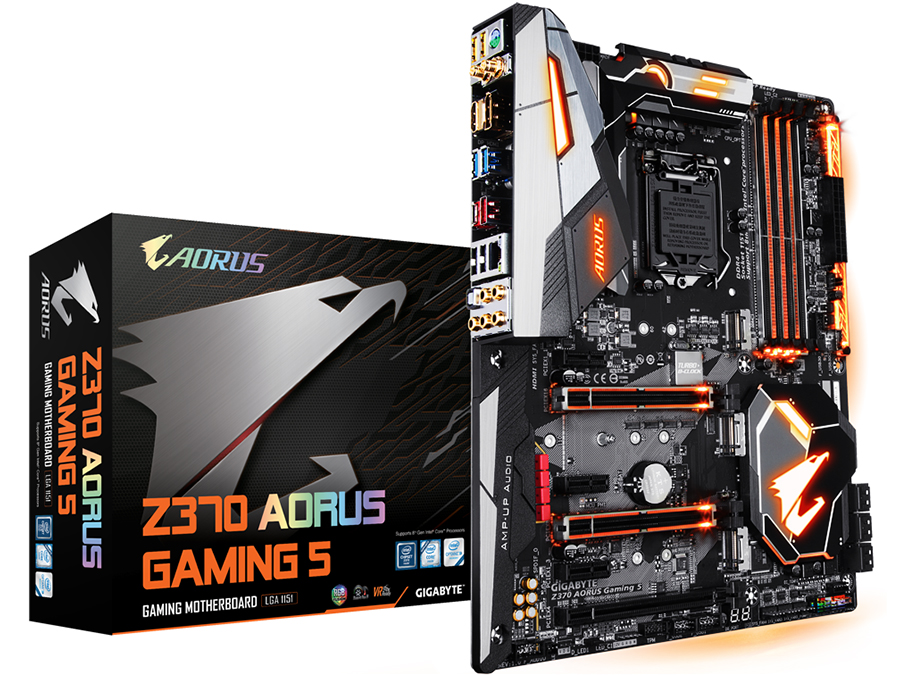
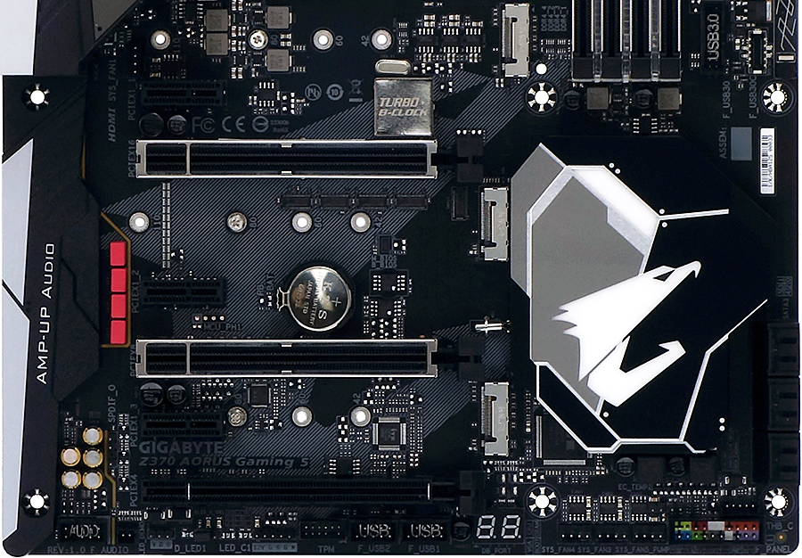
Gigabyte's Z370 Aorus Gaming 5 offers a more cost-conscious alternative to its big brother, the Z370 Aorus Gaming 7: Shaving the second Gigabit Ethernet port off the I/O panel, the firm also shaved $50 off the price tag while adding a low-cost Wi-Fi adapter. A few onboard buttons are also gone, along with the Gaming 7’s single M.2 heat spreader, but Gaming 5 buyers still get the three M.2 storage slots of its higher-priced sibling.
The company also kept the full onboard RGB package and associated light strip headers, but the value of those additions typically depends on the builder’s choice of case aesthetic. We'll treat this as a potential value bonus for RGB fanatics as we delve deeper into the Z370 Aorus Gaming 5's value credentials.
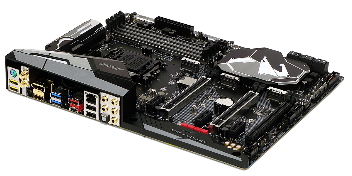
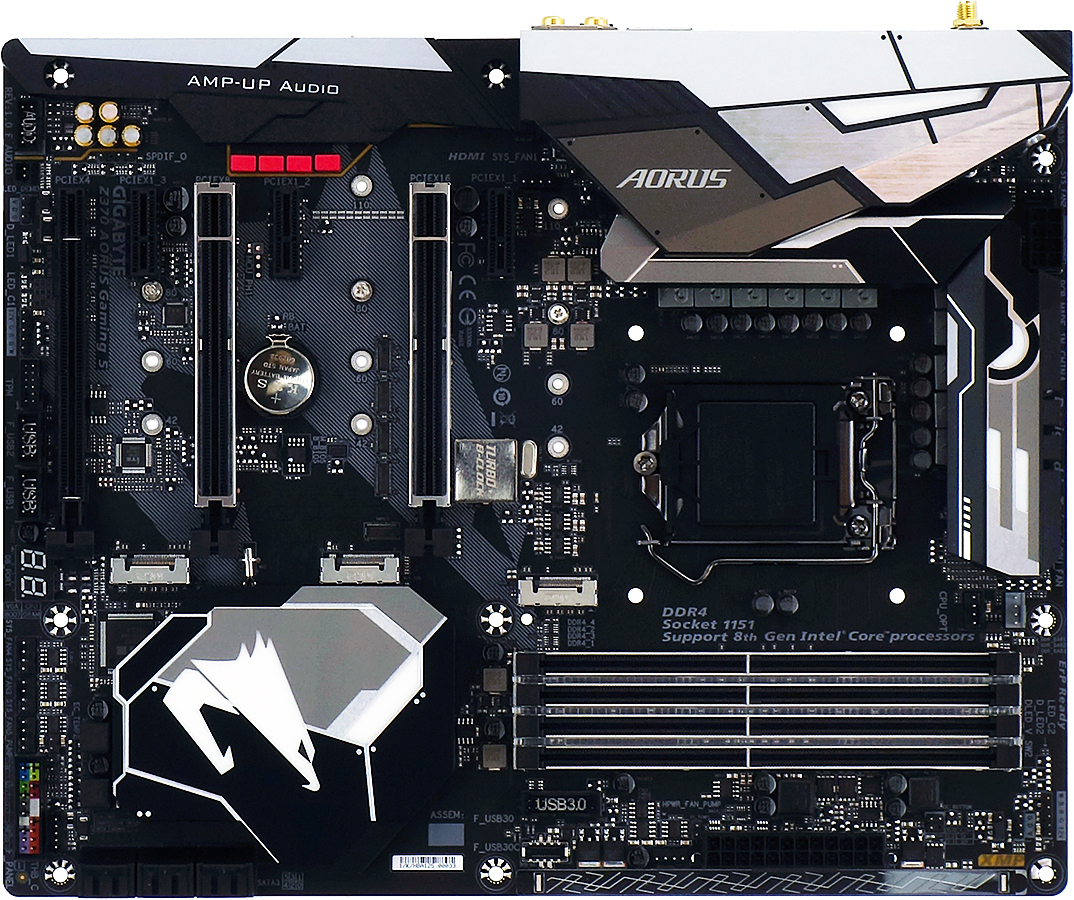
The Z370 Aorus Gaming 5’s layout looks strikingly familiar, from its triple M.2 storage and triple x16-length PCIe slots to its single Type-C USB front-panel header, yet a closer look at the specs reveals that the Type-C output is merely of the Gen 1 variety (aka USB 3.0), while a closer look at the long PCIe slots reveals that only two of these are lighted and surrounded by metal reinforcement. That last change should be considered purely aesthetic by most users, since both motherboard models limit the bottom slot to four lanes from the PCH, and it drops all the way down to two lanes when the bottom M.2 slot is occupied.
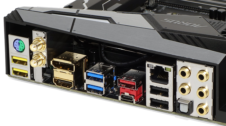
Changes to the I/O panel are a little more obvious, beginning with the absence of a second RJ-45 connector and the presence of two Wi-Fi antenna connectors. The USB ports have been rearranged to offer one additional Type A port, along two yellow “DAC-Up 2” USB 3.0 ports with adjustable voltage, two regular USB 3.0 ports and a USB 3.1 Gen2 Type A port that sits on the same 2-lane PCIe 3.0 controllers as the Type-C port. The final two ports are USB 2.0 and suitable for low-speed peripherals such as keyboards and mice.
As with the Gaming 7, the top M.2 ports of the Z370 Aorus Gaming 5 steal two HSIO resources from two SATA ports, regardless of whether they are loaded with SATA or PCIe based M.2 modules. The middle M.2 slot has a full set of PCIe lanes, and steals a SATA port only if an SATA module is installed.
The lower slot has no SATA connectivity, but does steal two lanes from the four-lane lower PCIe slot when filled. The top PCIe x1 slot steals an HSIO resource from an SATA port, so the worst-case scenario of having any M.2 drive in the first slot, an SATA M.2 in the second slot, and an x1 card in the top PCIe slot would leave builders with only two active SATA cable ports.
The two metal-reinforced LED-lighted PCIe slots switch from x16/x0 to x8/x8 mode whenever a card is installed in the lower of these two slots. That’s par for the course with Z370 motherboards, given the CPU interface’s ability to support sixteen lanes directly, and the ability of the CPU’s onboard PCIe controller to split those across up to three cards. Hardly any gaming motherboard has more than two CPU-fed slots because hardly any gamer wants to put a card on an x4 slot, though a few storage geeks were probably hoping for CPU-based NVMe via M.2.
Get Tom's Hardware's best news and in-depth reviews, straight to your inbox.
The Z370 Aorus Gaming 5’s bottom edge features an HD-Audio front-panel header, a power header for demonstrating LED lighting using a bare board, one (of two) addressable LED headers with voltage selector jumper, one (of two) RGBW LED strip header, a TPM module port, two USB 2.0 two-port headers, a two-digit diagnostics code display, three (of eight) four-pin fan headers, one (of two) thermistor lead headers, a CLR_BIOS jumper, a Thunderbolt add-in card header, and an extended front-panel switch/activity light header with the standard AC-97 pin arrangement on the left, a beep-code speaker and three-pin power LED header on the right, and a chassis intrusion header in the middle. The chassis intrusion header uses the “N/C” (not connected) pin typically found on Intel style power/LED headers as a ground.
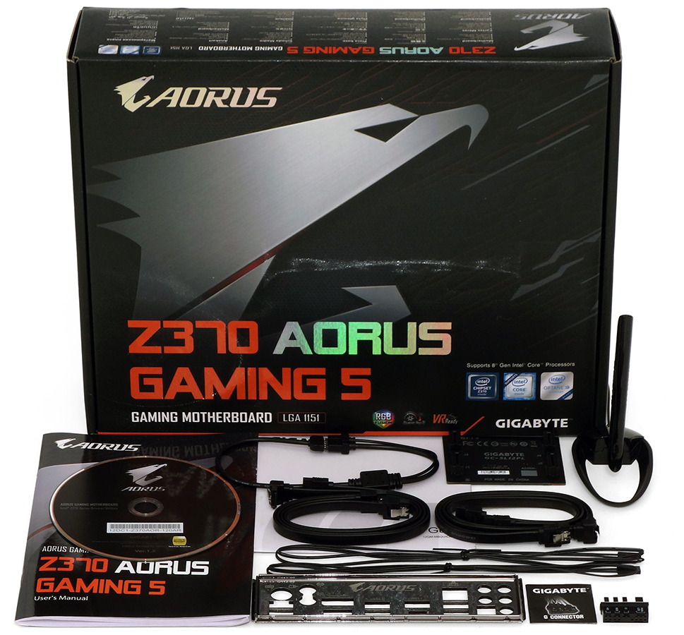
The installation kit includes the driver disc and documentation, an RGBW extension cable with detachable white lead, a high-bandwidth SLI bridge, a magnetic-base Wi-Fi antenna, four STA cables, two Thermistor cables, an I/O shield, and Gigabyte’s connector coupling for front panel activity LED/button leads.
Specifications
| Socket | LGA 1151 |
| Chipset | Intel Z370 |
| Form Factor | ATX |
| Voltage Regulator | 11 Phases |
| Video Ports | DisplayPort 1.2, HDMI 1.4 |
| USB Ports | 10Gbps: (1) Type-C, (1) Type A, 5Gb/s: (4) Type A; (2) USB 2.0 |
| Network Jacks | (1) Gigabit Ethernet, (2) Wi-Fi Antenna |
| Audio Jacks | (5) Analog, (1) Digital Out |
| Legacy Ports/Jacks | (1) PS/2 |
| Other Ports/Jacks | ✗ |
| PCIe x16 | (3) v3.0 (x16/x0/x4*, x8/x8/x4*, x8/x8/x2*) (*Two lanes shared w/3rd M.2) |
| PCIe x8 | ✗ |
| PCIe x4 | ✗ |
| PCIe x1 | (3) v3.0 (3rd slot excludes SATA port 1) |
| CrossFire/SLI | 3x / 2x |
| DIMM Slots | (8) (4) DDR4 |
| M.2 Slots | (2) PCIe 3.0 x4^ / SATA*, (1) PCIe 3.0 x4 (*Excludes ports 0, ^4-5) |
| U.2 Ports | ✗ |
| SATA Ports | (6) 6Gb/s (SATA M.2-2 takes pt 0, M.2-1 pts 4-5) |
| USB Headers | (1) 5Gb/s Type-C, (1) v3.0, (2) v2.0 |
| Fan Headers | (8) 4-Pin |
| Legacy Interfaces | ✗ |
| Other Interfaces | FP-Audio,TPM, (2)RGBW-LED, (2) D-LED, (2)Thermistor Header |
| Diagnostics Panel | Numeric |
| Internal Button/Switch | ✗ / ✗ |
| SATA/RAID Controllers | Integrated (0/1/5/10) |
| Ethernet Controllers | WGI219V PHY |
| Wi-Fi/Bluetooth Controllers | Intel 3165 802.11ac (433mb/s) / BT 4.2 Combo |
| USB Controllers | (2) ASM3142 PCIe 3.0 |
| HD Audio Codec | ALC1220 |
| DDL/DTS Connect | ✗ |
| Warranty | Three Years |
MORE: Best Motherboards
MORE: How To Choose A Motherboard
MORE: All Motherboard Content
-
sp5618 First-time PC builder does this board have a thunderbolt 3rd generation 40 MB? If not what motherboards in the ATX form factor Have it? Thank youReply -
Crashman Reply
Leave it empty?20951510 said:I don't know what to do with the third M2 slot
Chipset limitations are butting up against the desire to extend M.2 support: These companies want a third x16 slot with four lanes, and at least two NVMe M.2 slots, but that combination uses 12 of the 30 HSIO ports. Gigabyte added another NVMe M.2 slot that kills off a couple SATA lanes when its being used, I guess they could have just left off that M.2 slot, knocked the SATA port count down to four, and included a fully-utilized Thunderbolt controller instead.20951647 said:First-time PC builder does this board have a thunderbolt 3rd generation 40 MB? If not what motherboards in the ATX form factor Have it? Thank you
Nearly all of these boards are designed to host a Thunderbolt add-in card in the four-lane slot, but most of those slots require you to sacrifice some other interface. Look for the Thunderbolt add-in-card header.
On the other hand, Mini ITX has fewer slots, and several of those boards have Thunderbolt controllers to use up some of the leftover HSIO.
-
Crashman Reply
I realize that Gigabyte is using split-phase design. I've always hated counting phases because the number hasn't meant anything since companies came out with 24 low-amperage phases to compete with the six to twelve high-current phases of competitors back in the Core 2 days. I only include the easiest number because so many people don't understand what i just said.20951814 said:1 inductor does not equal 1 phase
-
android_dev It's a 8+3 phase with the voltage controller being a true 4 phase on the CPU section doubled to 8 with additional mosfet drivers while the other 3 are for iGPU.Reply -
Crashman Reply
I thought the other three were for the entire system agent, including the memory controller :)20976842 said:It's a 8+3 phase with the voltage controller being a true 4 phase on the CPU section doubled to 8 with additional mosfet drivers while the other 3 are for iGPU. -
android_dev Reply20976876 said:
I thought the other three were for the entire system agent, including the memory controller :)20976842 said:It's a 8+3 phase with the voltage controller being a true 4 phase on the CPU section doubled to 8 with additional mosfet drivers while the other 3 are for iGPU.
It's another voltage controller that controls the memory VRM which is a Richtek RT8120. The CPU Core Voltage VRM uses an Intersil 95866 which is a true 4+3 phase which Gigabyte has doubled to 8+3 phase. System Agent and VCCIO use Richtek RT8120D which is 1 phase each.
-
Crashman Reply
I didn't mention the memory signal voltage controller, for which the components can usually be seen separated from the group of things for various CPU devices ;)20976914 said:20976876 said:
I thought the other three were for the entire system agent, including the memory controller :)20976842 said:It's a 8+3 phase with the voltage controller being a true 4 phase on the CPU section doubled to 8 with additional mosfet drivers while the other 3 are for iGPU.
It's another voltage controller that controls the memory VRM which is a Richtek RT8120. The CPU Core Voltage VRM uses an Intersil 95866 which is a true 4+3 phase which Gigabyte has doubled to 8+3 phase. System Agent and VCCIO use Richtek RT8120D which is 1 phase each.
As for the 4/8, I say split, you say doubled. But getting back to the original message, we were seeing 24+ voltage regulators on P35/P45 boards before someone else (I think MSI) came out with higher capacity parts on a 6-phase design that could do the same work at lower cost. Soon after we were frying 12 phase regulator components and not frying 8 phase components when doing the same thing, because the boards with the 12 phase regulators were using substandard parts. Then some companies put high-amp chokes on low-amp MOSFETs and I blew more boards.Then some companies put high-amp chokes AND MOSFETs on the same board and extreme overclockers blew traces surrounding the MOSFETs. Then some companies used a thicker copper layer on the PCB with higher amp parts and hollow EPS12V pins and I blew out the connector. We even had sockets without enough contact pressure on the pins blowing out. Because of this, the only way I can find the weak point is through testing. And because of that, I'm now treating "phase count" as a matter of trivia.
-
android_dev Reply20977076 said:
I didn't mention the memory signal voltage controller, for which the components can usually be seen separated from the group of things for various CPU devices ;)20976914 said:20976876 said:
I thought the other three were for the entire system agent, including the memory controller :)20976842 said:It's a 8+3 phase with the voltage controller being a true 4 phase on the CPU section doubled to 8 with additional mosfet drivers while the other 3 are for iGPU.
It's another voltage controller that controls the memory VRM which is a Richtek RT8120. The CPU Core Voltage VRM uses an Intersil 95866 which is a true 4+3 phase which Gigabyte has doubled to 8+3 phase. System Agent and VCCIO use Richtek RT8120D which is 1 phase each.
As for the 4/8, I say split, you say doubled. But getting back to the original message, we were seeing 24+ voltage regulators on P35/P45 boards before someone else (I think MSI) came out with higher capacity parts on a 6-phase design that could do the same work at lower cost. Soon after we were frying 12 phase regulator components and not frying 8 phase components when doing the same thing, because the boards with the 12 phase regulators were using substandard parts. Then some companies put high-amp chokes on low-amp MOSFETs and I blew more boards.Then some companies put high-amp chokes AND MOSFETs on the same board and extreme overclockers blew traces surrounding the MOSFETs. Then some companies used a thicker copper layer on the PCB with higher amp parts and hollow EPS12V pins and I blew out the connector. We even had sockets without enough contact pressure on the pins blowing out. Because of this, the only way I can find the weak point is through testing. And because of that, I'm now treating "phase count" as a matter of trivia.
Hmm.. interesting, I was too young back then when you reviewed that stuff 10+ years ago now but yeah I read circuit analysis reviews of this motherboard and that's how I got the info for what I wrote above.
