Back-connect motherboards and GPUs have been popping up more than ever lately, thanks to various manufacturers adopting DIY-APE's designs and building upon them. You can find a bunch of options in the cable-less market now, but there are still some caveats, like the individual cables for all the components being separate. That changes today — with BTF 3.0 — the latest "Back to Future" spec from DIY-APE looking to finally eliminate cables altogether.
What DIY-APE wanted was a complete reinvention, with cables that are not only hidden from plain sight but also minimized to the point where they're genuinely more accessible. That's where BTF 3.0 comes in. It retains backwards compatibility with prior BTF versions but consolidates the GPU, CPU, EPS, and other connectors (not including front panel I/O) into a single 50-pin connector, using the ATX 3.0/3.1 standard from Intel.


This 50-pin interface, referred to as the "gold-finger solution," is capable of handling up to 2,145W, which DIY-APE quickly points out isn't unrealistic since many server power supplies using the CRPS standard are rated for even higher wattages. Out of the total 2,145W, the CPU and GPU get 1,680W. Here, DIY-APE proposes a universal answer to GPUs in BTF 3.0 by merging the best of both worlds that exist right now.
See, current back-connect graphics cards either use DIY-APE's own method of hiding the PCIe cables with a removable top cover, or Asus' proprietary implementation of a GC-HPWR connector on the GPU itself. BTF 3.0 motherboards will come with DIY-APE's own version of this connector (able to provide 1000W of power), but for GPUs that don't support it, a right-angle adapter will be provided to bridge the PCIe plugs on the card with the connector on the board.

The new gold finger solution will connect directly to a power supply with a female connector, but it will also be compatible with standard ATX 3.0/3.1 models using an adapter to convert conventional plugs into a single 50-pin connector. Front panel headers will be merged into a more compact, simplified layout, but won't be integrated into the 50-pin connector to maintain wide compatibility with the majority of cases out there.

That nicely bridges into the rest of the BTF 3.0 standard, as it goes beyond just the connector. BTF 3.0 is an all-encompassing mandate for clean, effortless PC building. For instance, the standard includes short-tube water cooling in AIOs, and each case is supposed to come with fan/RGB hubs with pre-routed wires channeled toward fan slots, or even USB-C ports in designated areas for swift hotswapping.


There are more specificities that DIY-APE highlights in the video, but the gist of it is that BTF 3.0 is not only a step forward — a significant one at that — but it's also a step in the right direction as it emphasizes backward compatibility, along with support for non-BTF parts with the use of adaptors. It's frankly a genius design if implemented right, but at the moment, it's just a concept.
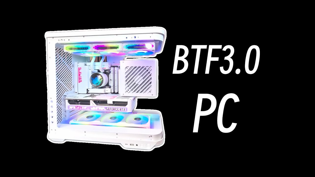
DIY-APE actually built an entire PC with BTF 3.0 prototype hardware from Colorful and Sego, and it looks slick. It's flawless from the front, with only the most minute wiring visible at the rear, but even that's meticulously routed to appear deliberate. Some details, like how to handle fans in the BTF 3.0 spec, still need to be finalized, and DIY-APE clarifies it's up to the manufacturers' courage to go all-in on this future.

Follow Tom's Hardware on Google News, or add us as a preferred source, to get our latest news, analysis, & reviews in your feeds.