QQC Q-Swap Power Bank Tear-Down
Do Touch This
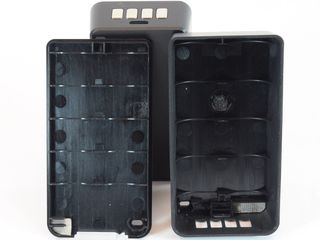
Once gutted, we can see both the top and bottom covers’ LED holes and small pieces of EMI gasket (tubes of metalized fabric stuffed with spongy material) in mirrored corners. The battery status LED is activated by proximity sensing, and those pads are responsible for increasing the touch feature’s sensitivity. It's a simple, yet effective touch. Of course, this is also one more manufacturing step driving cost up.
MORE: SilverStone PB06 USB Power Bank Tear-Down
MORE: Best Deals
The Q-Cell Cells
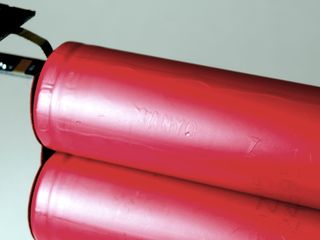
With the right lighting, camera angle, and some editing to increase contrast, we can barely see the Sanyo brand embossed into the cells’ sleeves. If you were about to point out that this contradicts the packaging’s claim of Panasonic cells, Sanyo has been a wholly owned Panasonic subsidiary since 2011. At QQC’s asking price for its Q-Swap kit, we wouldn't tolerate anything less than top-tier cells.
MORE: SilverStone PB06 USB Power Bank Tear-Down
MORE: Best Deals
Q-Cell Electronics
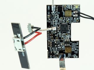
What lies at the heart of QQC's Q-Swap batteries? A Texas Instrument MSP430 micro-controller in 16QFN packaging runs the show with the assistance of several support components carrying those obnoxious and often undecypherable shorthand codes.
Stay on the Cutting Edge
Join the experts who read Tom's Hardware for the inside track on enthusiast PC tech news — and have for over 25 years. We'll send breaking news and in-depth reviews of CPUs, GPUs, AI, maker hardware and more straight to your inbox.
What is an MSP430? Simply, a micro-power 16-bit processor running at up to 16 MHz with proximity sensing features, 2KB of internal flash memory, 128 bytes of RAM, and a 10-bit analog-digital converter for the 2231 (top of its range) variant used here. While this may sound laughable by PC standards, it is strangely overkill for such a simple application.
MORE: SilverStone PB06 USB Power Bank Tear-Down
MORE: Best Deals
Q-Cell Soldering
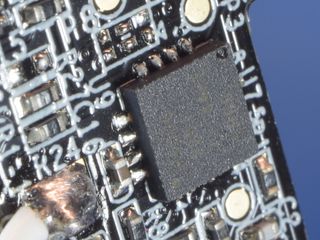
The soldering quality is generally good, though solder joint appearance is somewhat inconsistent between components, and even between the pads/pins of the same component on account of having slightly too much solder. Instead of slightly concave fillets from PCB pad edges to component contacts, the excess solder has a tendency to ball up on the affected joints. This is most evident around the QFN chip pictured here.
With that said, I’d rather have slightly too much solder, which may not look pretty under high magnification but is otherwise harmless, than being short by any amount and have a much higher likelihood of mechanically weak or intermittent connections.
MORE: SilverStone PB06 USB Power Bank Tear-Down
MORE: Best Deals
Q-Cell Contact, Inside Story
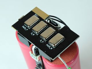
The Q-Cell’s contact slabs are soldered directly to the back of the board. As is common with battery packs, the first and last contacts are indeed battery (pack) negative and positive, while the pads designated D_P and D_N make it look like some form of differential signaling may be going on between the cell and frame.
In the bottom-right corner of the board, you can see the wire connecting the board to the cells’ negative terminal. Although you may not be able to tell at this picture’s resolution, the wire got tinned with just enough solder that the strands’ shape still shows through. We don't see perfect tinning like that very often. Of course, one sample isn’t enough to know whether this is a lucky accident or the norm.
MORE: SilverStone PB06 USB Power Bank Tear-Down
MORE: Best Deals
Q-Cell Charging Board
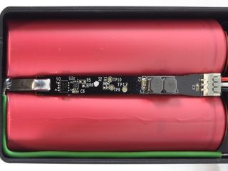
What do we find on that little charging board? It looks like a typical Li-ion charger arrangement. Starting from the cells’ negative terminals spot-welded to a metal strip on the left then soldered to the board, there is what appears to be a disconnect FET in leadless SO-8 packaging, a smaller control chip to the right with its handful of passive components to set limits, one “large” ceramic capacitor for the hidden switching regulator’s output, and its two tiny inductors that must be connected in parallel to handle 2.1A, as their wiring is approximately 0.18mm in diameter, or AWG #33.
To use such small filter components, the switching regulator’s operating frequency must lie somewhere beyond 1 MHz.
MORE: SilverStone PB06 USB Power Bank Tear-Down
MORE: Best Deals
Sensing Curiosity
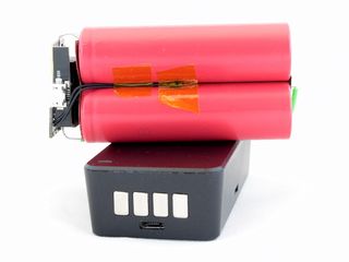
As is customary with lithium cells in responsibly-designed devices, a temperature sensor connected to the main board is tucked away and taped between cells. I would have expected this sensor to tie into the charger board instead, since monitoring temperature is more critical during charging to detect an overcharged or failing cell before something unpleasant happen. Good cells seldom fail during discharge unless they are grossly overloaded long enough to overheat. That shouldn't happen here, so long as the Q-Cell has sane current limits.
At first, I thought the white wire might be an enable signal for the controller to shut down the charger on overheat. One quick measurement revealed that it is simply a 5V USB feed for the main board.
MORE: SilverStone PB06 USB Power Bank Tear-Down
MORE: Best Deals
Under The Q-Cell Charger Board
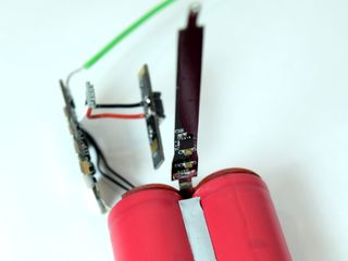
Seeing how power from the micro-B connector went straight to the narrow board between the two cells with no semiconductor in the immediate area, I desoldered one end of the board to have a peek at what lurked beneath.
Predictably enough, the only things hidden under there are two more ceramic capacitors at the input and a Li-ion switching charging controller. According to the only info sheet I could find about it, the ηETA6003 is capable of handling charging currents up to 2.5A at up to 95% efficiency and switching frequencies up to 3 MHz.
To help the tiny regulator cope with waste heat, a wedge of thermal pad material fills the gap between the two cells to help the chip leverage its cells as heat sinks.
MORE: SilverStone PB06 USB Power Bank Tear-Down
MORE: Best Deals
Charging Current
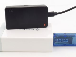
When I first charged the unassembled Q-Cell, I noticed the charging current rapidly dropping from 2.1A to 1.6A as its inductors became unbearably hot. Tapping my fingers on the inductors to cool them down caused the charging current to momentarily rise back to 2.1A. Charging the factory-new sealed cells produced a drop all the way to 1.3A from the same initial 2.1A shown here, albeit without the Q-Cell’s case developing any noticeable hot spot.
Since tap heat-sinking the bare inductors had such an immediate and significant effect on charging current, I suspect QQC could have used inductors with bifilar wiring to reduce I2R and skin effect losses.
MORE: SilverStone PB06 USB Power Bank Tear-Down
MORE: Best Deals
Q-Boost Frame
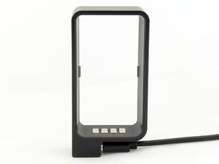
Did the name inspire the shape or did the shape inspire the name? Either way, if you were still wondering how Q-Swap relates to the actual product, I believe this image is self-explanatory.
The thin Q-Boost frame has a pair of tiny tabs on its long walls that lock onto Q-Cells with a satisfying click and hold them with a reasonable amount of force. The fit between the frame and cell is quite snug, which is necessary for the cell to make good contact with the frame’s pads at the bottom. On the other side of the contact area, we have the type-A socket opening sideways from the Q’s tail.
With no cell inserted, the long walls feel flimsy. Insert a battery, though, as I presume these are intended to be carried, and they may survive being accidentally sat on sideways.
MORE: SilverStone PB06 USB Power Bank Tear-Down
MORE: Best Deals
-
JamsCB Interesting idea, but by going with this design of a spare battery with exposed contacts means you're going to have to do something with that extra battery if you want to fly anywhere, at least in the US (See the regulation: 49 CFR 175.10(a)(18) ). Personally I feel if you need that much spare charge, two separate banks would be the simpler and cheaper option.Reply -
sparkyman215 Asus makes a great battery pack with 10k mAh, and it's only $20. I've had mine for maybe a year and it hasn't exploded yetReply -
LostAlone Feels like this is entirely misguided on their part. Battery packs are bulk commodity items now, they've become cheap and ubiquitous. Everyone has their own branded ones out there. And with that in mind, I just don't understand an expensive version. Honestly, even in the corner case that you need so much juice that multiple battery packs are reasonable then I'd rather have another complete back with it's extra ports available. Sure, a little more bulk but only slightly and this gives me a truly redundant solution that I can lend to someone or have a complete spare in the event of loss or damage.Reply
In the end, given that battery packs are already light and small making a lighter smaller one isn't that big a deal. Any thing in the 10k mAh range is too big to keep in a pocket all day anyway, and once you're tossing the things in a bag then it really doesn't matter if it's a little big smaller or lighter. -
Daniel Sauvageau Reply
People stuff 6" 'phones' in their pockets. I've seen 10Ah power banks smaller than those but haven't tested one yet to see if they can actually deliver. I do plan to address that later this year.19802041 said:Any thing in the 10k mAh range is too big to keep in a pocket all day anyway
-
nukemaster Another good one.Reply
Looking forward to seeing your tests on some of those smaller 10Ah ones you mention. I rarely need an on the go charge(my old Zen did sometimes when I forgot to charge it), but it is always nice to have 5 volts for testing things. -
LostAlone ReplyPeople stuff 6" 'phones' in their pockets. I've seen 10Ah power banks smaller than those but haven't tested one yet to see if they can actually deliver. I do plan to address that later this year.
Phones have a bigger footprint but a 10k or 12k battery back is MUCH thicker and MUCH heavier. Take it from someone with a big phone AND a 12k battery pack; only one of those happily lives in my pocket all day. Maybe on something with cargo pockets you could stick the battery in a pocket but it wouldn't be comfortable to sit on it.
My battery pack is almost an inch thick dude; and totally inflexible and heavy enough that it can pull your pants down. It's a whole other kettle of fish compared to a phone, even a big phone. -
alextheblue I'll just shove this into my pocket with loose change...Reply
They need some kind of spring-loaded safety cover for those contacts, and at that price I would want so much more than what they're offering. Standard cylindrical cells? I would expect it to be using fancier (and higher density) packs using semi-prismatic cells or maybe higher-end well-engineered pouch cells.. Maybe support for Qi charging and higher amp output / higher volt QC capabilities. Otherwise... it's really no better than a typical 5200 pack in the $30 range. -
Daniel Sauvageau Reply
That depends heavily on the type of cells being used and by type, I mean the actual chemistry and geometry of the cell which dictate the cell's maximum charge/discharge current, cycle endurance and nominal capacity. There is a drastic energy density difference between high current, high endurance cells (thicker current-carrying electrodes and anode/cathode material) and those prioritizing energy density over all else.19805518 said:Phones have a bigger footprint but a 10k or 12k battery back is MUCH thicker and MUCH heavier.
Also, a power bank designed around pouch-style cells isn't constrained by the size of 18650 cells and can be made much thinner. -
Daniel Sauvageau Reply
Based on my limited short-circuit tests, that should actually be fine as the output cuts off within 2ms from the short being detected and wouldn't cause your change to warm up noticeably.19805743 said:I'll just shove this into my pocket with loose change...
Still, I am disappointed that there wasn't some sort of protocol between the pack and frame to limit current until the connection to an accessory is confirmed.
Most Popular


