Hacksawing a Motherboard Helped Me Set a 12900K Overclocking Record
I set a Cinebench world record on Alder Lake by destroying a motherboard.
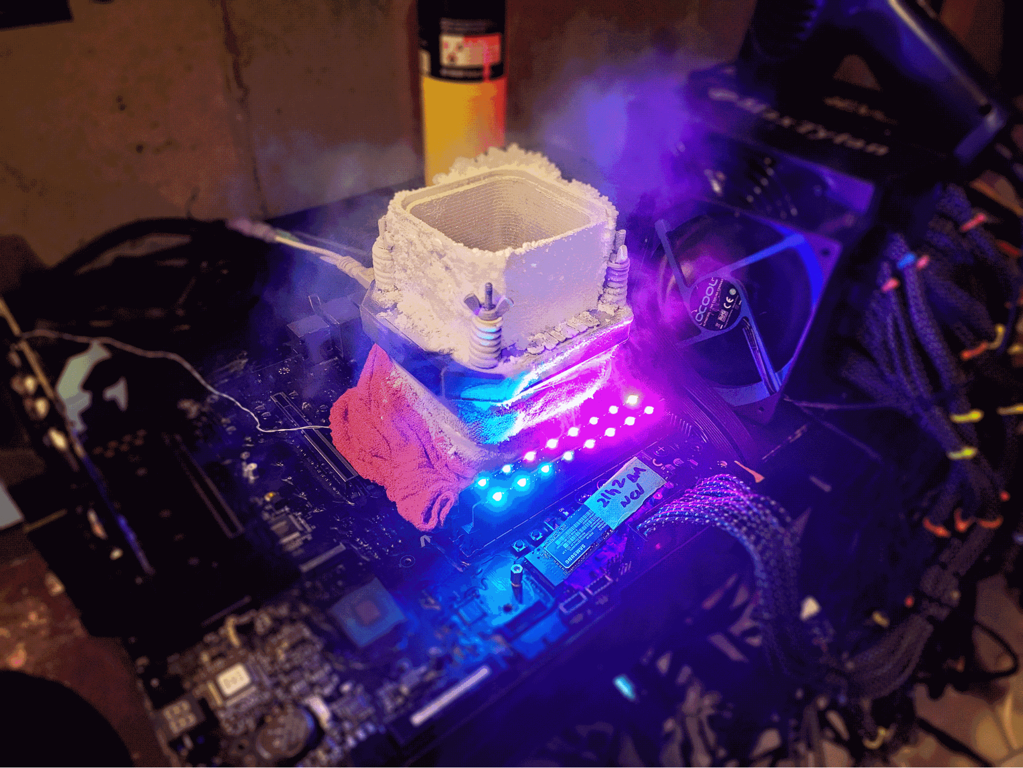
Intel’s Alder Lake has retaken the performance crown from AMD, but in some cases, chip bowing issues have resulted in sub-par cooling. I took a hacksaw to a motherboard to help fix the issue, resulting in an extra 50 MHz of clock speed that put me over the top, winning a world record with the Core i9-12900K in Cinebench R23 at 6.95 GHz.
It has been a couple of weeks now since we got the first wind about Intel’s Alder Lake chip bowing problems, which is the result of Intel’s Z690 socket hold-down mechanism (ILM) having issues that can cause the chips to bend. The dust has seemingly settled on this topic, as news cycles tend to do, and the YouTubers are already taking facepalm photos for the next outrage that they come across (we can only guess what it will be). But, I am not finished, and neither is famous overclocker and entrepreneur Der8auer.
Intel’s Z690 is here, and there will be refreshes (we already know the 12900KS is coming), and then Z790 will arrive and I’m almost certain we will see the same type of speed bumps. Therefore it is worth the time to investigate this as an extreme overclocker looking for an advantage to improve performance and to cover why I wouldn't recommend some of the mods you might have read about.
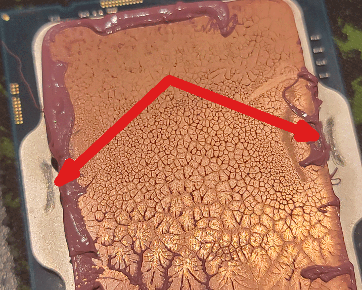
Intel has used a lever-action hold-down mechanism, known as an Independent Loading Mechanism (ILM), on LGA mainstream motherboards for seemingly ever. The single-sided dual-point-of-contact mechanism holds the chip snug in the socket, and it can even cause scratches that you see left behind on your heat spreader when you disengage the ILM to remove your CPU for the socket (that’s actually a good way to tell if a chip is used or not).
Intel’s ILM is simple, has always done the job fairly well, and seems to hold up great over time. In fact, you could demonstrate the mechanism to a six-year-old, and after a couple of seconds, they would get the idea of how it works. I have an LGA775 motherboard that has had chips inserted and removed over a thousand times, and it's still just like new. So why are there issues now with the new LGA1700 sockets for Alder Lake?
I want to start by saying there is nothing technically wrong with the mechanism. Intel designs it and conducts numerous safety and reliability assessments during the design process. If you take a look at the socket blueprint and read the specs, it is mind-blowing — Intel specs a myriad of factors, including the required pin contact pressure and torque specifications for the screws. If anything, Intel’s socket designs tend to be over-engineered.
As such, if you put a Core i9-12900K on a motherboard, it will perform to its rated specification, but overclockability is not guaranteed. Much like with tuning a car engine, I could produce 50 horsepower more by flashing the ECU in my car to increase the boost pressure. Does that mean my stock car is trash because the manufacturer did not give me that horsepower from the factory? No, it doesn't. It has the horsepower it is designed to have, much like a 12900K runs the frequency it's rated for. But due to human nature, I want to go faster, and we can, so let’s find a way to add more horsepower to Alder Lake CPUs.
Now, time to make some suggestions for improvements. This project started off with my frustration with the poor contact between the chip and my liquid nitrogen CPU container. Knowing that I had already flattened my CPU heat spreader by lapping it, which means I sanded the surface down to be completely flat, and that the bottom of my CPU container was also machined and lapped flat, I was confused why the thermal paste in the middle of the chip was so thick.
Stay on the Cutting Edge
Join the experts who read Tom's Hardware for the inside track on enthusiast PC tech news — and have for over 25 years. We'll send breaking news and in-depth reviews of CPUs, GPUs, AI, maker hardware and more straight to your inbox.
Make no mistake, thermal paste can be the weakest link in the cooling system. Thermal paste is a gap filler, and while we want it as thin as possible, we also want enough that we have complete contact across the entire top of the chip. Here are six different Core i9-12900KFs that I binned, showing the possible variation from chip to chip. This is why extreme overlockers lap their CPU — we want the best possible contact with a very thin layer of paste.
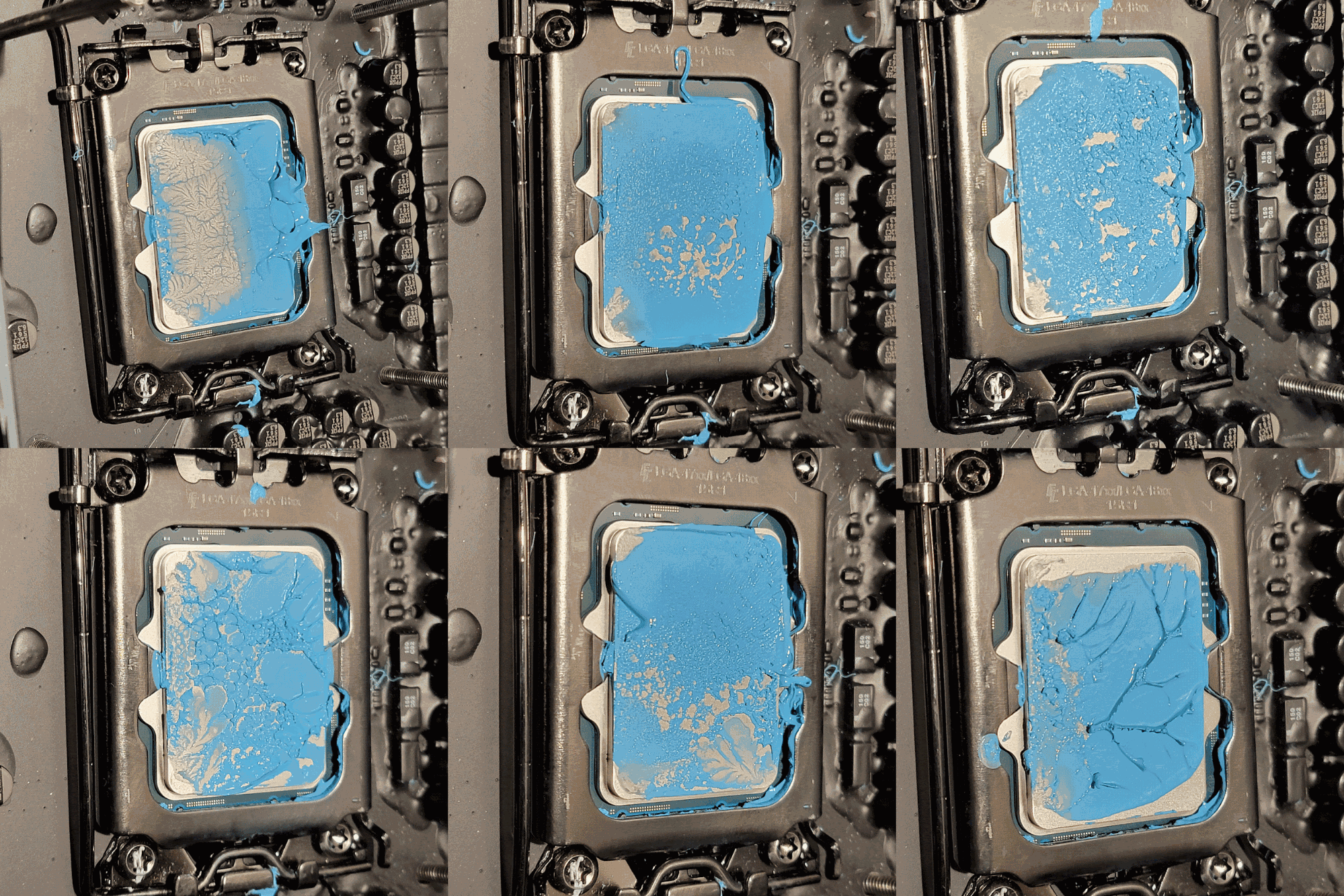
The thick paste we see here robs me of precious extra CPU megahertz during extreme overclocking because it reduces cooling capabilities. However, after studying the CPU’s integrated heat spreader (IHS) more, you begin to notice that the top and bottom edges of the heat spreader are holding the cooler up like it's on stilts. In some cases, the edges are so high there isn’t even any thermal paste spread there, causing the IHS to scratch your cooler when you twist it off.
I lapped my best CPU (see below) as I usually do, but it didn’t help my mounts look any better. The paste was still thick in the middle, and there wasn’t any paste on the top and bottom quadrants. How is this possible if I lapped the CPU and the cooler on calibrated flat glass?
I suspected that the hold-down mechanism, which only contacts the very middle edges of the CPU, was flexing the middle of the chip down, causing the top and bottom edges of the CPU to bow upward. How can I test this?
I came up with the idea to simulate the CPU inside the socket while it's under tension from the hold-down mechanism, and then re-flatten the CPU by lapping it while the chip is still bowed.
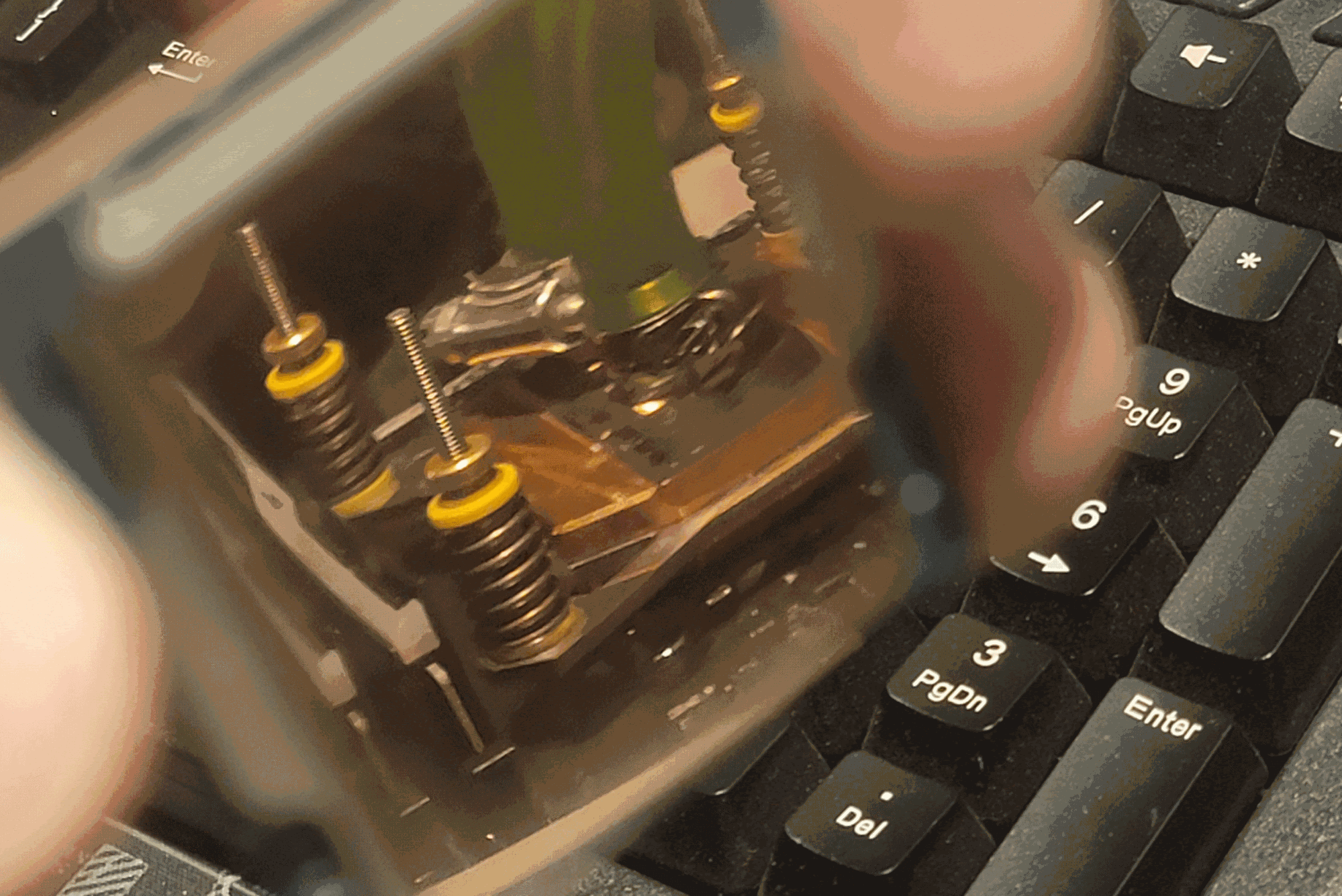
By simulate, I mean I took a hacksaw and cut the socket out of a $1300 ASRock Z690 Aqua OC that was sent as a sample.
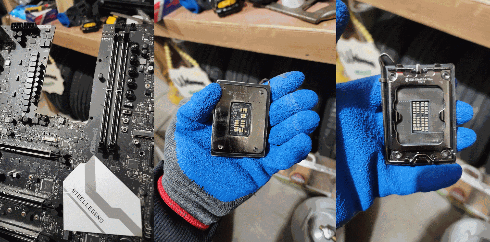
Here is a look at the jig that I made, and just as I anticipated, the socket’s ILM flexes the CPU hard. I use grid lines to show where the material is being removed, and you can see the high points at the very top and bottom of the CPU in the images below.


Why is it like this? My guess is that there is a required pin contact pressure, and we might be reaching the limit of this type of hold-down with Alder Lake’s more rectangular and long design. Perhaps a double-sided system, a la X299, would perform better. However, that certainly would cost more and is less user-friendly, not to mention that this current method does actually work.
As I stated earlier, the design meets Intel’s specifications. Imagine being in a meeting at Intel as an engineer pitching the idea of using a more complicated hold-down mechanism that costs potentially 50% more, and your reasoning is that it may reduce the temperature of your CPU by 5c or so at stock settings. That might not go over well.
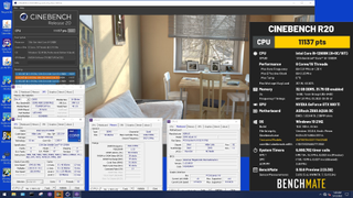
So I'm pretty excited at this point — it’s 2 am, and I'm in my basement sanding away with a grin on my face, daydreaming of my potential clock speed gains from finding this solution, and I’ll be damned! I gained 50 MHz on the top end under liquid nitrogen after re-lapping the CPU, which was enough to smash the world record for the eight-core Cinebench R20 category on HWBot with 11,137 points at 6.95 GHz.
My Record-Breaking Core i9-12900K Setup
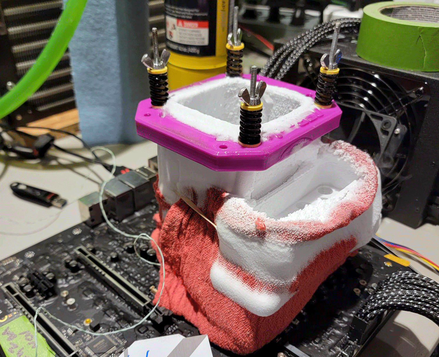
- Intel 12900K
- ASRock Z690 Aqua OC Motherboard
- Team Group Hynix DDR5 RAM
- Thermal Grizzly Extreme Paste
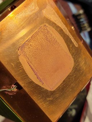
After finishing the extreme overclocking session, I was so excited to see how it looked when I unscrewed the LN2 pot. When I removed the CPU cooler, the contact was pristine. I was totally beyond satisfied with the nice thin, even spread of the paste and full coverage of the chip. The extra 50 MHz that improvement yielded was just enough to put me over the top. The adrenaline was flowing; this was the highest I had been able to push the 12900K!
At this point, I began to think of what I could do so that myself and others could benefit from this, but without the extreme measures of hacksawing a motherboard and then sanding down the processor.
Whenever I have a decent idea, I usually call Der8auer and brainstorm. We get the ideas flowing, and mine are usually junk, and his are genius, naturally. No lie, he had a prototype solution made the next day and then shipped it to me within a week. He’s insane. Now, there are patents pending, so I can't show you yet what the device looks like, but I can say it more than matches my solution of sanding down the chip, and you should keep your eyes on his YouTube channel for when he drops it! It’s a total game-changer.
I want to touch on a couple of mods that I have seen online that don’t fix the problem entirely but can help increase performance. One mod uses washers under the hold-down mechanism to mitigate some of the downward pressure, thus reducing the bowing effect. In my opinion, this will work, but I would avoid doing it for a few reasons. First, the ILM is created to provide a certain amount of pressure to assure the chip has proper contact with the pins, and while this mod does remove some of the bowing, it affects the pin contact pressure as well. This could negatively affect stability, and in the worst case, you could lose a memory channel.
A similar method is just to loosen the hold-down mechanism’s screws. But by how much? Who knows — it's all a gray area. For most people, doing this on a $500+ motherboard and chip is risky for the minimal gain. Another mod I have seen is using a replacement top for the ILM, but it mimics the original Intel design and only contacts the same two points on the sides of the chip, which introduced the flex in the first place. I can only guess that maybe the modded ILM is looser, introducing the same potential problems with lower-than-spec pin pressure.
The last mod I’ve seen is to remove the hold-down mechanism completely. I admit I tried this one, and I killed a motherboard by bending all the pins in one corner when I removed the cooler. I later found out it wounded the chips’ memory controller, too, and now dual-channel memory no longer works on the chip. That was a frustrating day.
I will never fault anyone for coming up with ideas to improve performance, though; I’m just giving my opinions on them. To everyone else, I would suggest being patient. There are some commercial solutions on the way. If you can’t wait and can afford to destroy an expensive motherboard, you could grab your own hacksaw, but the performance gain isn’t worth the money for most people.
A world-champion competitive overclocker who frequently tops the charts at HWBot, a site which tracks speed records, Allen will do just about anything to push a CPU to its limits. He shares his insights into the latest processors with Tom’s Hardware readers from a hardcore, push-it-to-the-limit overclocker’s perspective.
-
btmedic04 i for one couldnt imagine in the days of the great silicon shortage of 2020-present, hacksawing a $1300 motherboard to harvest a socket to gain 50mhz. more power to you for doing it, but oofReply -
hotaru251 TBH surprised some vendor hasnt sold "flattened" cpu's to sell to ppl interested in OC.Reply
yes, its small subsection, but it exists and ppl would pay for a pre lapepd one (as many ppl are scared to do it themselves) -
Sluggotg Fun Stuff! I am sure Intel will come out with a new design to address this. But that leaves me with 3 Alder Lakes with Bowed CPUs. I think they will be fine for a while but at some point we could see physical failures on the chips like Micro Cracks or CPU Package Distortions.Reply -
w_barath ReplySplave said:Hacksawing a Motherboard Let Me Set a 12900K Overclocking Record : Read more
You had all the right ideas, you just didn't combine them with dedication. That's what led to hacksawing the MOBO, which was unnecessary if you had stuck to your original knowledge.
Lap the CPU and IHS. Install the hold-down mechanism, with screws threaded from the backside of the MOBO. Install with minimal thermal paste. Back off the hold-down mechanism screws from the back of the MOBO (don't remove, leave pinky-finger tight, and later tighten them before removing the heatsink.)
Tada. 0 patents pending required.
Most Popular


