Tripp-Lite isobar Surge Protector Tear-Down
What Has Been Seen
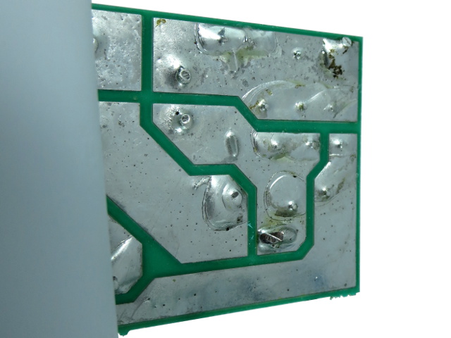
Pulling back the loose half of that sheet reveals a similar fluxy solder job to what we saw in January's TL606 tear-down. The bottom-right trace goes directly to ground and, looking at the solder joints, we can conclude there is one MOV across N-G, one across L-G and two across L-N in this cluster.
The rest of the circuit that cannot be observed from the board edges will need to be figured out the old-fashioned way: continuity testing and intuition.
Traced Out
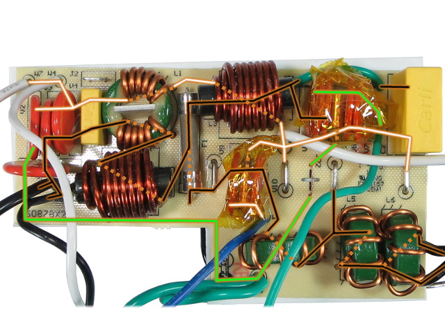
Traced lines on this image correspond to PCB connections, while dotted lines represent connections through inductors or fuses. Imagine where the components' leads are to figure what they are connected to.
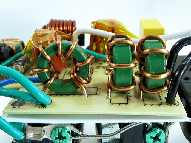
As I suspected, the “isolated banks” are only one inductor apart. More surprisingly, those inductors are wired in series between outlets. I have doubts as to how well the isolation would perform in the presence of a significant noise current.
Introducing Some Noise
How do you test noise filtering or isolation? You inject noise and measure how much of it shows up where it is not supposed to. I'm using a vacuum cleaner as my noise source. Although it's not the most scientific test instrument, it should prove more than adequate for demonstration purposes.
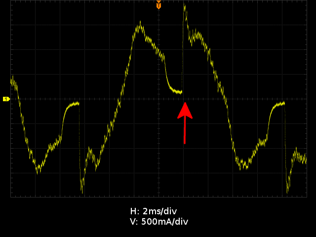
The trace shows the current waveform after adding a 700Hz high-pass filter to attenuate 60Hz current by about 21dB. Our point of interest is the 2A step in 100µs at the red arrow occurring two milliseconds after every zero-crossing due to the electronic power controller.
Rigged For Testing
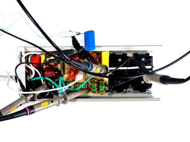
To measure voltages at each output, probes are hooked up to components inside the isobar. Channel one is connected directly at the fuse, channel two connects to the tinned part of the toroidal inductor's lead, while channels three and four connect to the back of their respective outlets. The blue cap provides a bypass path between scope ground and the isobar's neutral to reduce common-mode noise.
Get Tom's Hardware's best news and in-depth reviews, straight to your inbox.
How well-isolated do you think the banks actually are? Let's have a look. The following waveforms are taken at the switching point mentioned on the previous slide, since that is where noise should be at its worst. The traces are offset for enhanced visibility.
First Bank
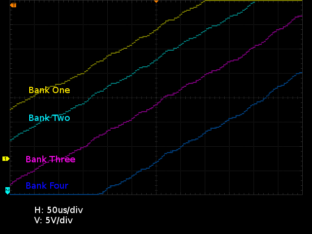
With the vacuum connected to a first bank outlet, there is nearly no visible noise on any of the four banks. You might even think I got the horizontal and vertical scales or offsets wrong, or forgot to turn the vacuum on. This is exactly what I was expecting. The isobar's 1µF X2 capacitor connected almost directly across bank one eats practically all electrical noise, leaving little to contaminate the other banks strung after it.
Second Bank
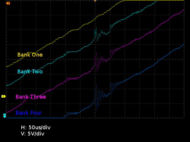
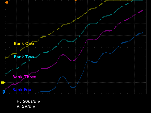
Now the vacuum is connected to the second bank, one toroidal inductor downstream from the first bank and X2 cap. As before, the first bank shows negligible noise. But the second bank does have about 5VPP from current change through the inductor. I was expecting it to get transposed directly to the third and fourth banks since they are connected through series toroidal inductors, however, noise actually doubles to 10VPP on bank four. It appears the inductors have a self-resonance frequency of about 100kHz.
How much difference would plugging something in bank four to load it down make?
Second Bank, Take Two
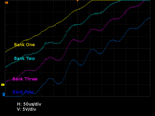
I used a spare computer power supply to provide light loading. As expected, the ringing frequency dropped to 12kHz or so, courtesy of the PSU's 1µF X2 cap in its EMI filter. But the magnitude still doubles between bank two and four.
This may shed some light on why Tripp-Lite mentioned the isobar might not be suitable for all uses. Interactions between reactive components can form resonant circuits, generating unexpected voltages and frequencies that could be problematic for sensitive equipment.
Fourth Bank
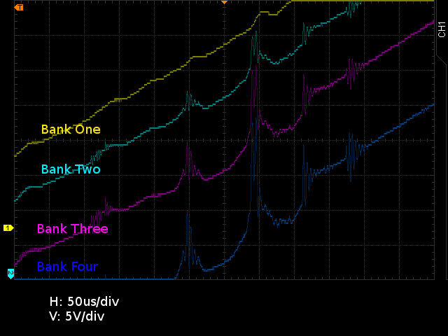
This time, the vacuum is connected to the last bank, the one after all three series inductors. Voltage spikes scale proportionally at 5V per bank, starting from negligible noise on bank one and peaking at 15V on bank four, exactly as you would expect from a voltage divider.
My vacuum's current slew rate is about 20mA/µs, which is at least an order of magnitude milder than truly nasty noise sources, so the isobar's inductors could possibly end up generating well over 100V worth of voltage noise from current.
Fourth Bank, Take Two
With both the vacuum and PSU connected to the fourth bank, oscillations similar to the second bank with our PSU on the fourth return, except the waveform gets distorted more severely. Again, the noise amplitude scales linearly with the number of inductors between the reference (bank one) and the other banks.
Isolation?
I really like the isobar's mechanical design, and the use of regular outlets instead of stamped metal strips is also a welcome change.
Electrically, the input filter should do a fine job at filtering line noise and blocking most surge energy. However, the four allegedly isolated banks are a let-down. Performance looks more like you have bank one, and then everything else since the series inductors fail to provide anything I would consider as meaningful isolation. In fact, for the limited testing done here, the isobar would have been better off without them. Tripp-Lite could easily improve this by wiring its toroidal inductors to a common live point instead of cascading them, which looks like a significant oversight to me.
Aside from the design concern above, there is no doubt the isobar has the beefiest filtering and surge protection featured in these tear-downs so far.
Questions? Comments? Suggestions? Leave your message down below or PM me.
-
blackmagnum "How many people actually use their power bars' outlet covers?" I do. They protect the power bar from pest such as ants, pets and toddlers.Reply -
Kewlx25 My only wish is they had a 10 port version. I have a lot of low wattage electrical devices to plug in and the warranty says plugging this into another surge-protector or plugging another surge-protector into it voids the warranty.Reply
I've tried to find a non-surge-protecting power strip, but no luck. -
ralanahm Thank you for the review. I am glad to see these turned out better than lower price ones and it wasn't all marketing hype.Reply -
cbrunnem whats up with this guys/sites hard on for power strips.... can you not think of better things to review?Reply -
ralanahm Thank you for the review. I am glad to see these turned out better than lower price ones and it wasn't all marketing hype.Reply -
nukemaster Reply15622774 said:whats up with this guys/sites hard on for power strips.... can you not think of better things to review?
The community reaction to the early power bar tear down was positive.
If you do not want to see these, just do not read them.
This author is very good at breaking these things down so users can see and understand what is happening inside the power bars they sell at the store.
Tom's Hardware has other reviews and reviewers. -
froozeball Thank you both for the review and the chance (ie the actual product) to review!Reply
Always insightful, well presented and very useful. Frankly it's about time somebody really tore down, explained, and held these products accountable to the public. You explain issues to the point, good or bad, and it's a great piece of technology journalism that you present.
Felicitations et merci! -
Daniel Sauvageau Reply
All the sub-$15 power strips I have looked at are simple MOV affairs: power cord -> switch/breaker -> MOV(s) with thermal fuse -> outlets. For most electrical applications, they are indistinguishable from a plain strip unless something goes wrong since a 20D201K MOV conducts less than 1mA until voltage passes 200V. Under normal circumstances, 120V line voltage peaks at 170V so the MOV does practically nothing. You may also want to consider the fact that most of your electronics with a line-operated switchmode PSU likely has an EMI filter and MOVs of their own, which means they have much more complex impedance than a basic surge-protecting strip.15622264 said:I've tried to find a non-surge-protecting power strip, but no luck.
The warning against daisy-chaining surge protectors is more about the possibility of loose connections between strips degrading protection on downstream strips, over-loading strips and other issues which may affect surge protection performance or safety.
I have a few different things in the works but I need to put together a few test jigs first to make my life easier. If you do not like power-related accessory tear-downs, you are free to not read them.15622774 said:whats up with this guys/sites hard on for power strips.... can you not think of better things to review?
That said, I am starting to run out of tear-down candidates in that department, so I plan to do something else every other month to stretch those out, like the LCD tear-down/repair that came out last month. -
Daniel Sauvageau Reply
It is comments like those that make the ridiculous number of hours it takes to put these things together worth it. The tear-downs may look very simple but between planning, workbench and editing time, I likely spend more than an hour on average on each slide that makes it in.15623007 said:Thank you both for the review and the chance (ie the actual product) to review!
Always insightful, well presented and very useful. Frankly it's about time somebody really tore down, explained, and held these products accountable to the public. You explain issues to the point, good or bad, and it's a great piece of technology journalism that you present.
Felicitations et merci! -
gtinut heat shielding material? you must kidding. It is standard to place no conductive layer on metal where components are located.Reply
