PCB Bottom

MORE: APC BN650M1-CA UPS Tear-Down
MORE: CyberPower EC350G Tear-Down
MORE: How (And Why) We Test USB Power Adapters
Soldering

Through-hole soldering quality looks great, while the surface-mount soldering is slightly sub-par. Most of the surface-mount pads actually look fine. However, excess solder balls up on random components; the pictured one is a glaring example. Although it looks like it might not be attached to anything from the angle shown, it clearly makes contact with the resistor and pad from the opposite angle.
MORE: APC BN650M1-CA UPS Tear-Down
MORE: CyberPower EC350G Tear-Down
MORE: How (And Why) We Test USB Power Adapters
Spark Gap

When I first started searching for the closest points between primary and secondary on the PCB's bottom side, I was surprised to not find an obvious spark gap (where two pointed pads face each other across an isolation slot). While checking down there to see if the Chemi-Con capacitor got assistance from an MLCC capacitor, I noticed two little points approximately 7.5mm apart.
A proper spark gap should be narrower than any other clearances between the two sides. Here, though, you probably need to look more than once to determine that the gap distance is slightly shorter than the distance between the opto-isolator pads.
MORE: APC BN650M1-CA UPS Tear-Down
MORE: CyberPower EC350G Tear-Down
MORE: How (And Why) We Test USB Power Adapters
Gap Improvement

I would have liked to see something along the lines of what my edited image shows: the two points brought a few millimeters closer together and a millimeter-wide anti-tracking slot routed in front of the points. One wider slot between the two points would have worked as well.
Actually, since the board already has two 3mm holes under the transformer for no apparent reason, simply relocating one hole between those two points would have been a zero-cost improvement.
MORE: APC BN650M1-CA UPS Tear-Down
MORE: CyberPower EC350G Tear-Down
MORE: How (And Why) We Test USB Power Adapters
Sink Surprise

When I saw a TO-220 on the output heat sink, I immediately presumed that it was just a diode (as is almost always the case in small power supplies). Then I looked at the bottom of the board and noticed that its three terminals were completely separate, with an unexpected amount of circuitry connected to one of them. Naturally, I had to take a closer look.
Using my USB microscope, I managed to read the device’s number. It turned out to be a SemiHow HRP45N08K 4.5mΩ, 80V N-channel FET. I wasn’t expecting synchronous rectification, which explains the extra secondary winding for the driver’s supply and the circuitry cluster connected to the MOSFET’s gate.
MORE: APC BN650M1-CA UPS Tear-Down
MORE: CyberPower EC350G Tear-Down
MORE: How (And Why) We Test USB Power Adapters
Output Circuit

Starting from the output rectifier and transformer in the bottom-right corner and going left, current passes through the three CapXon caps with the fat traces necked down at each capacitor pad to focus current on the capacitor pins, maximizing their effectiveness. At the left end, current passes through a parallel pair of 7mΩ resistors for current sensing, a 1206 MLCC for noise reduction across the current shunts, and then goes off to the outputs’ dedicated circuitry (consisting of one 0603 MLCC for local decoupling, a fuse, and a CW3002D multi-standard adapter identification chip).
If you look closely, you’ll notice that the leftmost fuse is noticeably darker than the four others. As you may have guessed, that’s my blown port.
MORE: APC BN650M1-CA UPS Tear-Down
MORE: CyberPower EC350G Tear-Down
MORE: How (And Why) We Test USB Power Adapters
Start-Up Voltage

How much input AC voltage does the UC01 need to start up, and how low can it go afterward? The output goes live at a hair above 32VAC and stays on until the input voltage drops to 20VAC.
MORE: APC BN650M1-CA UPS Tear-Down
MORE: CyberPower EC350G Tear-Down
MORE: How (And Why) We Test USB Power Adapters
Capacitor Discharge Test

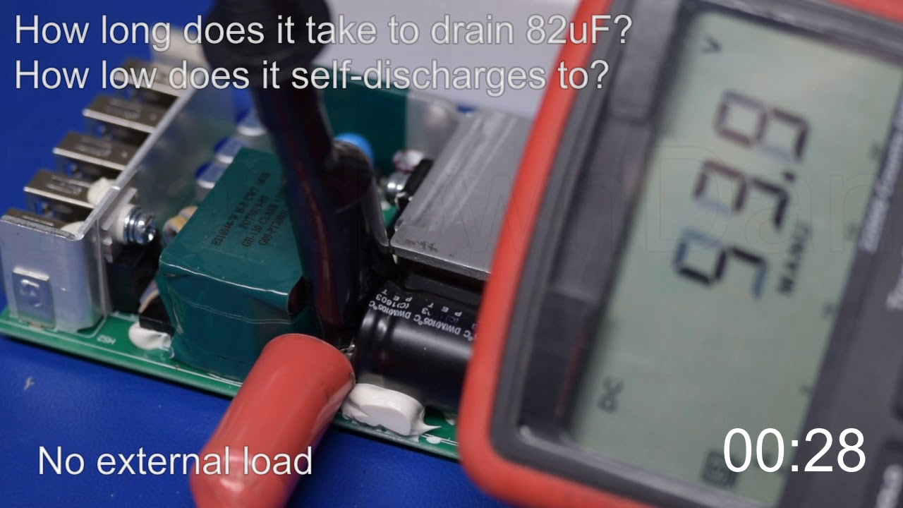
Any time someone opens a power supply, dire warnings are issued about shock from capacitors maintaining potentially deadly voltages for a very long time. While I agree that some caution is warranted, the dangers are often over-stated.
To illustrate this, here I am monitoring voltage across the UC01’s bulk storage capacitor. Under a 1A output load, the capacitor’s voltage drops to less than 10V faster than my multimeter can update. With no external load attached, the discharge time increases to 30s.
Switching power supplies do a thorough job of discharging their input capacitors in short order. With that said, not all designs are created equal, and you're still better off safe than sorry.
MORE: APC BN650M1-CA UPS Tear-Down
MORE: CyberPower EC350G Tear-Down
MORE: How (And Why) We Test USB Power Adapters
Standby Power

And now, back to our regularly scheduled testing, starting with how much power this adapter consumes merely being plugged in. On 115V, integral power weighs in at 39mW, which almost doubles to 73mW at 230V input. Both are comfortably within the 100mW Level VI efficiency class.
Why is there a ~20mA phase-shifted peak current, though? Simple: the UC01’s input filter has a 330nF X-class capacitor so...
XC = 1/(2πfC) = 1 / (2π × 60Hz × 330nF) = 8038Ω
I = V / XC = 162VPk / 8038Ω ≈ 20mAPk
This phase-shifted current comes entirely from the X-class capacitor.
MORE: APC BN650M1-CA UPS Tear-Down
MORE: CyberPower EC350G Tear-Down
MORE: How (And Why) We Test USB Power Adapters
Efficiency

Just like any power supply, efficiency starts somewhat on the low side under light loads due to quiescent power accounting for a disproportionate amount of total input power. From 5W on 115V and ~7W on 230V, the UC01’s efficiency remains above 85% all the way through its 8A/40W stated rating. The over-current limit kicks in at 8.65A, and efficiency is still at least 82% by the time that happens.
Compared against Level VI efficiency requirements, the UC01 is well ahead through most of its range. It barely squeaks by at 35W, while measurement error margins give it the benefit of the doubt at 40W.
MORE: APC BN650M1-CA UPS Tear-Down