Super Flower Leadex Gold 550W PSU Review
Super Flower has made quite an impact on the PSU market. Its Leadex platform enjoys huge popularity, both under SF's brand name and other companies like EVGA. The newest Leadex Gold-rated PSU with 550W capacity is on our test bench today.
Why you can trust Tom's Hardware
Transient Response Tests
Advanced Transient Response Tests
For details on our transient response testing, please click here.
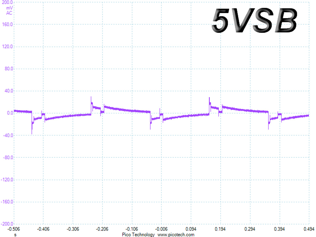
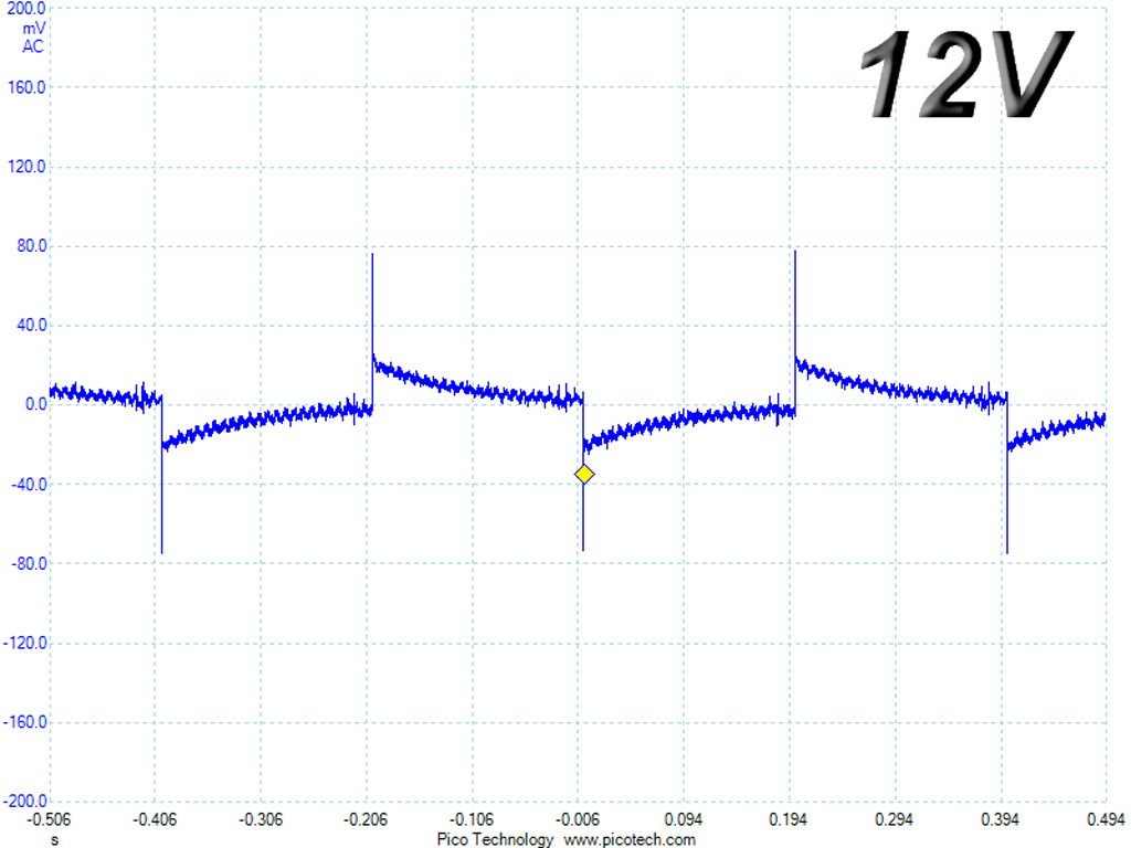
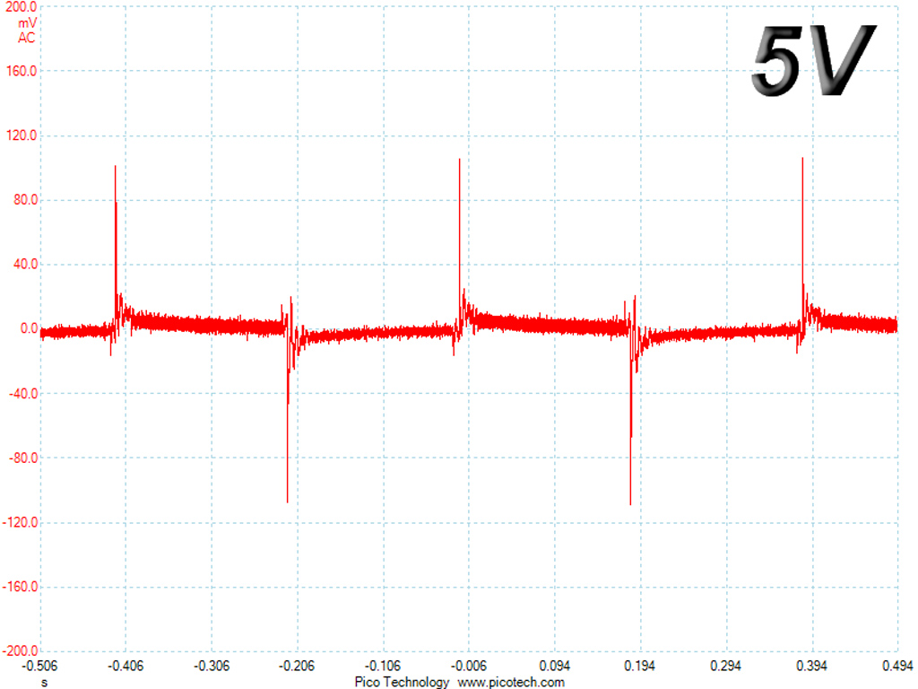
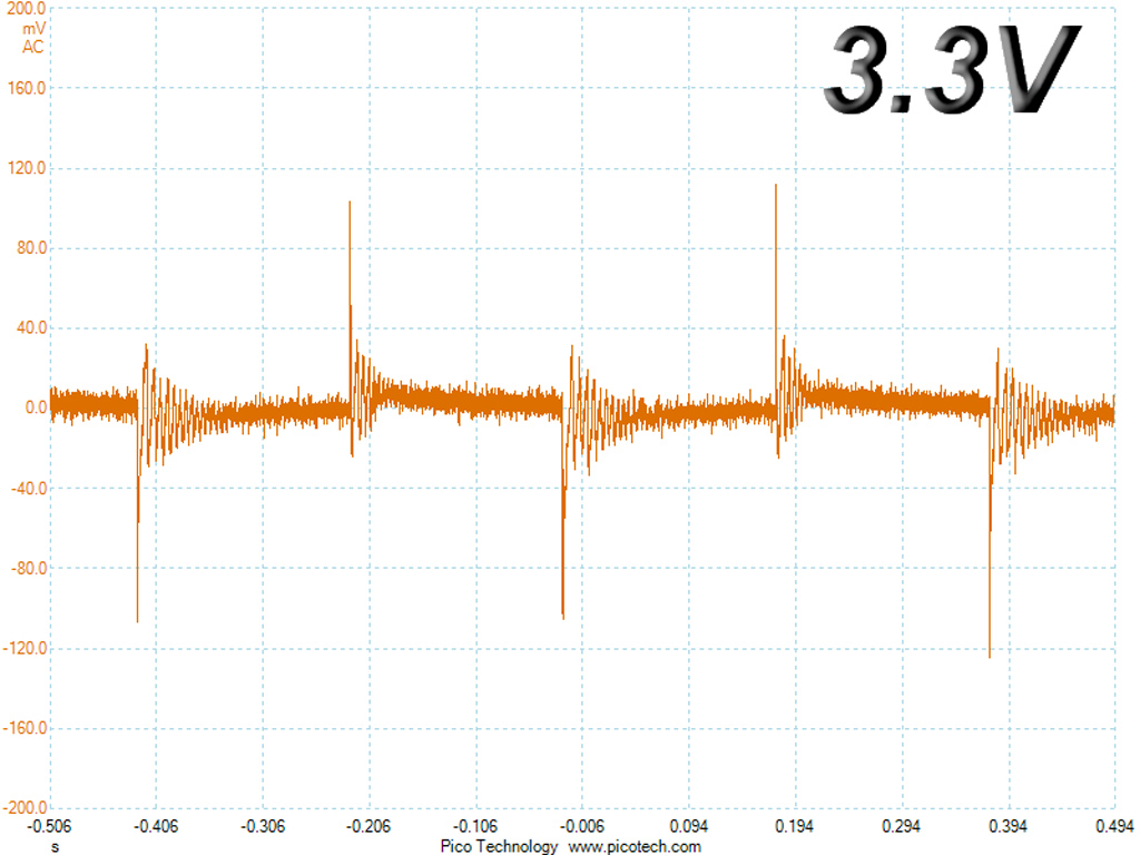
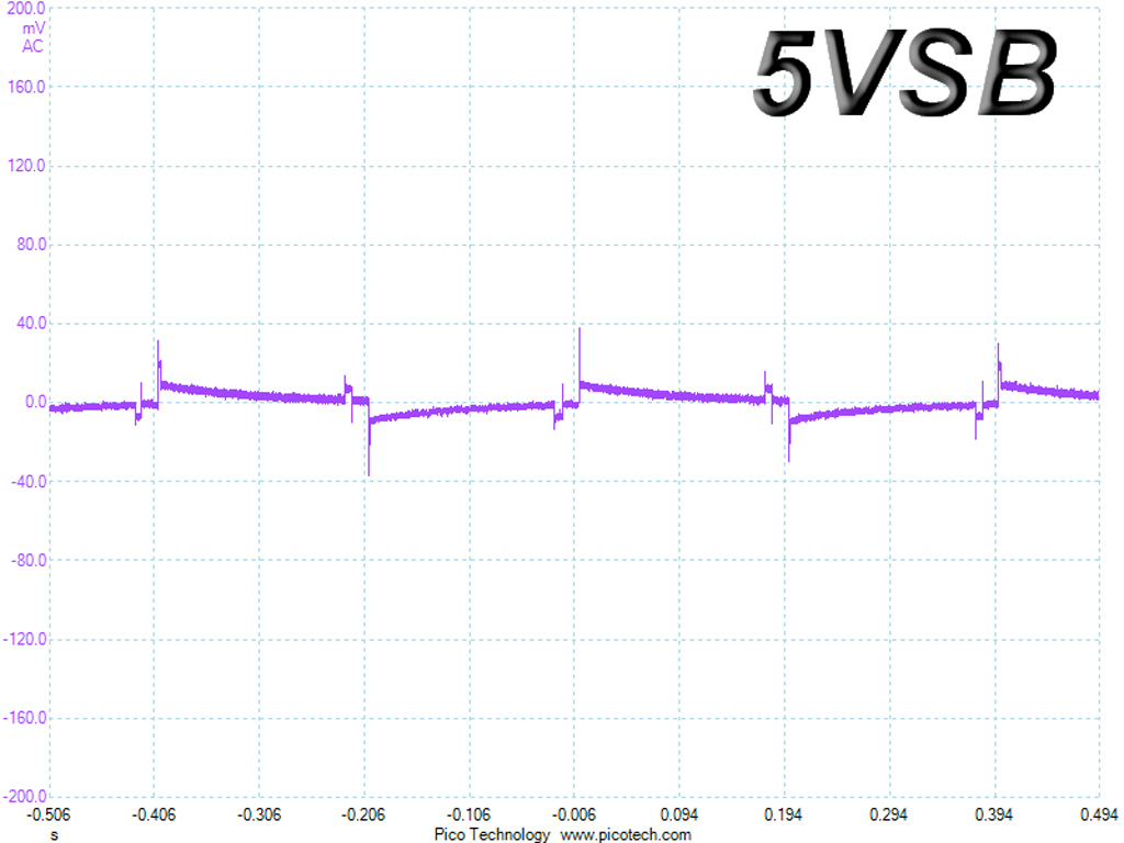
In these tests, we monitor the response of the PSU in two different scenarios. First, a transient load (10A at +12V, 5A at 5V, 5A at 3.3V and 0.5A at 5VSB) is applied for 200ms while the PSU works at 20 percent load. In the second scenario, the PSU is hit by the same transient load while operating at 50 percent load. In both tests, we use our oscilloscope to measure the voltage drops caused by the transient load. The voltages should remain within the ATX specification's regulation limits.
These tests are crucial because they simulate the transient loads a PSU is likely to handle (such as booting a RAID array or an instant 100 percent load of CPU/GPUs). We call them "Advanced Transient Response Tests," and they are designed to be very tough to master, especially for PSUs with less than 500W capacity.
Advanced Transient Response at 20 Percent
| Voltage | Before | After | Change | Pass/Fail |
|---|---|---|---|---|
| 12V | 12.314V | 12.231V | 0.67% | Pass |
| 5V | 5.022V | 4.913V | 2.17% | Pass |
| 3.3V | 3.316V | 3.183V | 4.01% | Pass |
| 5VSB | 5.062V | 5.028V | 0.67% | Pass |
Advanced Transient Response at 50 Percent
| Voltage | Before | After | Change | Pass/Fail |
|---|---|---|---|---|
| 12V | 12.279V | 12.193V | 0.70% | Pass |
| 5V | 5.013V | 4.906V | 2.13% | Pass |
| 3.3V | 3.310V | 3.175V | 4.08% | Pass |
| 5VSB | 5.022V | 4.988V | 0.68% | Pass |
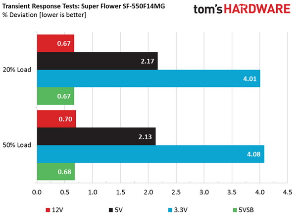
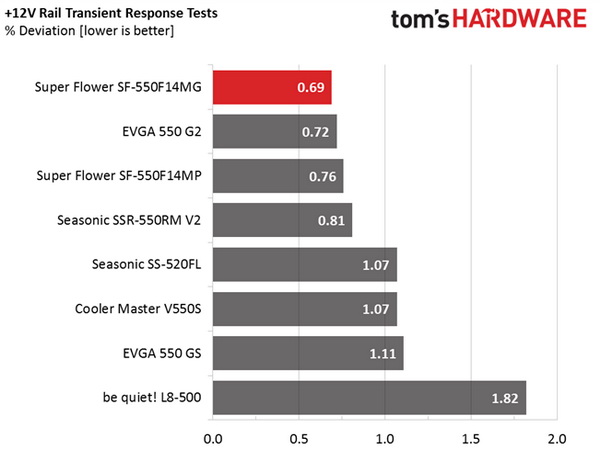
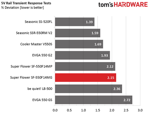
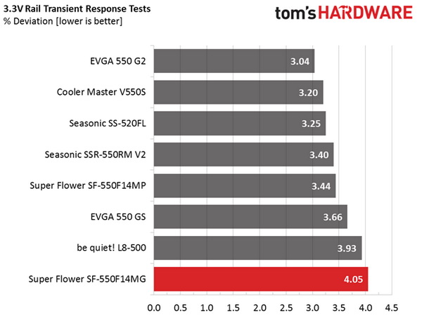
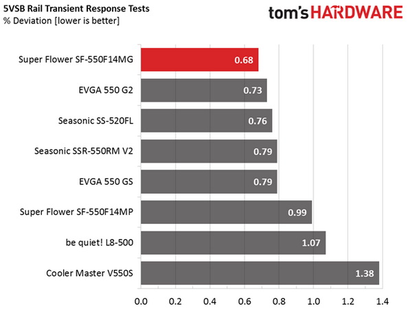
The +12V rail performs well in these tests. This comes as no surprise since that's usually the case with PSUs that use the Leadex platform. Super Flower does a very good job with its +12V, 5V and 5VSB rails. However, we cannot say the same for the 3.3V rail, where the deviations exceed four percent in both cases and the voltage drops below 3.2V once we apply the transient load.
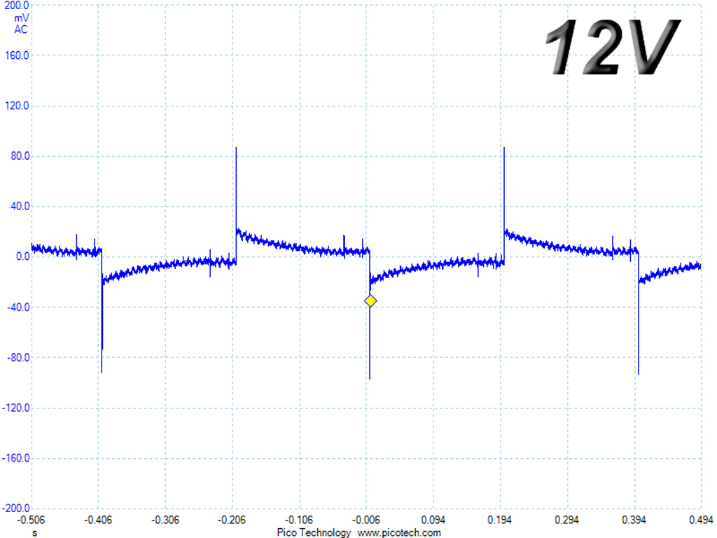
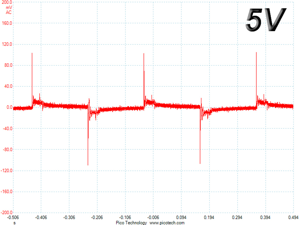
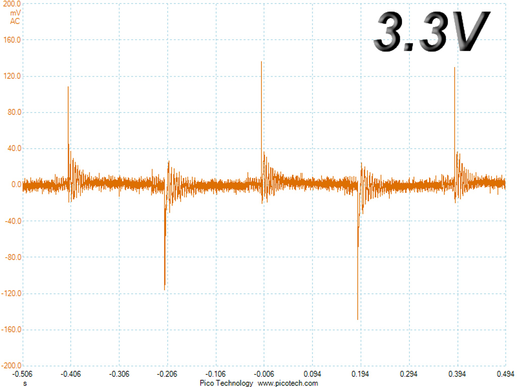
Here are the oscilloscope screenshots we took during Advanced Transient Response Testing:
Transient Response At 20 Percent Load
Transient Response At 50 Percent Load
Turn-On Transient Tests
In the next set of tests, we measure the PSU's response in simpler transient load scenarios—during its power-on phase.
For the first measurement, we turn off the PSU, dial in the maximum current the 5VSB can output and switch on the PSU. In the second test, we dial the maximum load the +12V can handle and start the PSU while it's in standby mode. In the last test, while the PSU is completely switched off (we cut off the power or switch off the PSU by flipping its on/off switch), we dial the maximum load the +12V rail can handle before switching on the PSU from the loader and restoring power. The ATX specification states that recorded spikes on all rails should not exceed 10 percent of their nominal values (+10 percent for 12V is 13.2V, and 5.5V for 5V).
Get Tom's Hardware's best news and in-depth reviews, straight to your inbox.
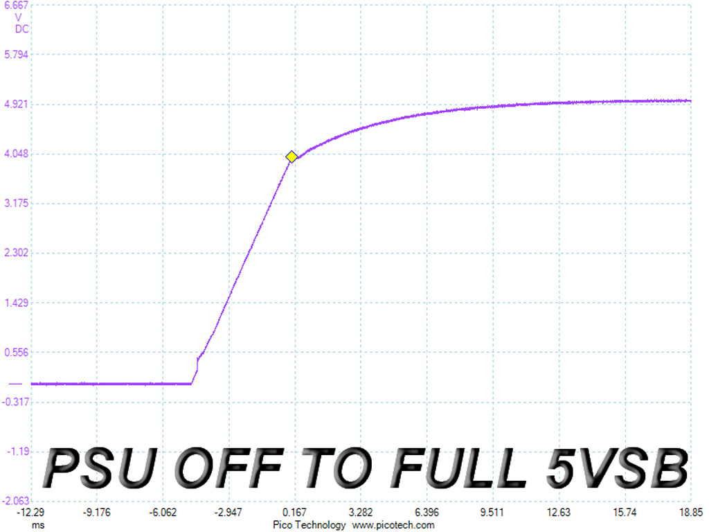
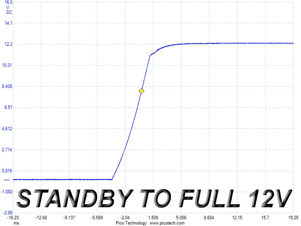
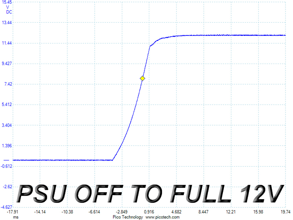
The turn-on tests appear fine since we don't notice any voltage overshoots or spikes.
Current page: Transient Response Tests
Prev Page Cross-Load Tests And Infrared Images Next Page Ripple Measurements
Aris Mpitziopoulos is a contributing editor at Tom's Hardware, covering PSUs.
-
blazorthon Granted the EPS and PCIe wires don't see very high current in most situations (especially the EPS with Haswell or Skylake CPUs), I hardly ever see other PSUs using thinner gauge wires, so I can't imagine it saving enough money to be worth going thinner than the recommended 18 gauge wires most other PSUs have regardless of capacity.Reply -
Quaddro Why crapxon?Reply
I'm tired to see bulged crapxon..
If this one use jap caps, it'll be absolutely perfect.. -
mctylr ReplyUnfortunately, the bridge rectifier's markings are on its hidden side, and we try to avoid desoldering these type of parts since they are extra sensitive to increased heat
Huh? Since when are bridge rectifiers particularly heat sensitive? I would say that bridge rectifiers are not worth the hassle to desolder, unless you suspect it was an underrated part.
APFC controller is an NCP1653A provided by ON Semiconductor. It's installed on a small vertical PCB and is covered by insulation tape in order to decrease EMI noise.
That looks like paper and vinyl / PVC electrical tape wrapped around the vertical PCB, which provides electrical isolation only, I doubt it would make measurable difference in EMI. -
Aris_Mp According to my experience so far they are, unfortunately.Reply
This provides some EMI protection. There is no need for electrical insulation on this board. As for the degree or EMI protection I can examine this with my EMC probes (once I find the time to do it). -
Andi lim this review said uses a half-bridge topology, I only see one main capacitor. half bridge usualy uses 2 main cap and 2 main switcher right ?Reply -
Aris_Mp the number of APFC caps has nothing to do with the primary topology. However yes half-bridge uses 2 switchers.Reply -
Andi lim You are right, this is half bridge with LLC series resonant converter, nothing wrong with the primary capacitor.Reply