PSU Repair: A Case Study
When your PSU won't start, most enthusiasts don't go beyond a paperclip or multimeter check. Today, we'll do a comprehensive repair of Antec's old SL300.
Capacitor Postmortem
What sort of state were those capacitors in? Let's revisit them using a simple pulse generator and a voltage divider made of two 2kΩ resistors in series. I would expect a good capacitor to reach 63% of the applied voltage after one time constant where τ = RC in seconds. Another area of interest that can be observed with this simple test setup is the first microsecond of the charge curve. Any abrupt voltage change there would be indicative of significant series resistance. Since I am using a voltage divider, keep in mind that the Thevenin equivalent would be a source of half the voltage with 1kΩ series resistance.


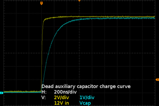
First up is the dead 680µF cap from the 5VSB output. In principle, its time constant should be 680ms. But here, it reaches 63% of its final value near the 120ms mark, pegging its capacitance to somewhere in the neighborhood of 120µF. The capacitor reaches a final voltage of 5.3V, which is 300mV short from the applied voltage, implying a 300µA leakage current. Based on the typical 0.01CV leakage current formula, this is over three times worse than the 68µA expected.
Zooming in to see the first microsecond of the charge curve reveals a 60mV step, a telltale sign of significant series resistance: at 1µs, an ideal 100µF should be showing less than 56µV here, so the early voltage rise shown in the first 400ns or so is clearly dominated by ESR. Working through the voltage divider equation yields an equivalent series resistor value of about 11Ω. Based on Teapo's spec sheet, which appears to have an error on it since my 680µF cap here is 8x15 yet the sheet says 8x11, the ESR should be 0.11Ω. In other words, this old cap is two orders of magnitude out of spec on ESR.
I went back in the power supply to pull out the other 680µF cap I had to reuse and did quick checks for thoroughness' sake. The 63% time was spot-on for 680µF, leakage at 5V was 5µA and the initial step was 20mV, indicating an ESR of about 4Ω. While this is better than the first one, it is nowhere near good enough to call a definitive fix. If I put this supply into a PC and started pulling some current off 5VSB, the weak cap's ESR would make it overheat and fail in short order. The extra ripple this may cause on the auxiliary cap would also contribute to its premature failure.
Based on Teapo's specifications, these capacitors are only good for up to 640mA ripple current, which might be on the low side for a 2A flyback. The RMS ripple current on a discontinuous mode flyback converter can reach 80-90% of the DC output current. Had the 5VSB section been designed for long life at full load, the capacitor accepting energy from the transformer should have had at least a 1.6A RMS ripple current rating. Many people would be quick to blame “bad caps”, but even the best caps on Earth would still fail when operated at double or triple their rated ripple current. In this case, the capacitor used is almost certainly under-rated.
Having one dead and one dying cap on the 5VSB output certainly explains why the new cap was so effective at reducing 5VSB ripples, even while connected at the end of the ATX power cable.
Now, let's have a second look at my other two replaced caps.

Next is the auxiliary supply's 47µF cap. It reaches 63% in 140ns, putting its capacitance in the ballpark of 140pF, effectively the same as my multimeter once you subtract the 20pF or so worth of test leads and scope probe capacitances. Where leakage is concerned, I got less than 1µA. No surprise there from a capacitor that failed open.
Looking up Fuhjyyu's TN-series specifications turns up the following information about this 5x11mm capacitor: only 500 hours endurance rating and 82mA RMS current, 164mA if you keep it below 70 ºC, about 200mA for frequencies above 1kHz. These may seem like absurdly low specifications, but for a capacitor that does little more than feed 100mA or so to the main PWM chip for its operation and the MOSFET gate drive, it likely is adequate under normal circumstances. My FC replacement is rated for 615mA at 105 ºC, or about 520mA if derated to 1kHz, vastly exceeding the Fuhjyyu's specifications.
Also worth noting are the 30-40V peaks across the auxiliary cap in my first set of auxiliary capacitor voltage measurements with the old part in. This capacitor is only rated for 25V, which is already a tight margin for a 20V nominal output not counting switching transients. The tight voltage margin means its protection against flyback peaks depends entirely on the 5VSB capacitors.


Last is the PWM's 22µF bypass capacitor. Going by the 63% point, its capacitance falls in the neighborhood of 16µF, which is in line with the multimeter result. However, the charge curve has a 300mV step immediately after test voltage application, translating to a series resistance in the neighborhood of 57Ω. As far as leakage goes, this one is also under 1µA at 12V.
Going through the TN-series specs once again turns up that this capacitor has a nominal ripple rating of 52mA, or about 150mA after applying multipliers, which is likely also fine since this capacitor only needs to help deliver gate current drive pulses to turn the main MOSFET on. Here, my FC replacement is rated for 220mA after applying 1kHz derating, again more than a match.
When all of the capacitors on a flyback power supply's outputs have failed, there is little left standing in the way of flyback operation generating high voltage spikes and destroying components. From the state these caps were in, with peaks up to 40V showing up across the 25V auxiliary capacitor that were likely worse before I freshened the 5VSB caps, I am really surprised the magic smoke had not come out already. Also, depending on the one capacitor that failed open and another with sky-high ESR for gate drive current, they could have easily caused sluggish MOSFET turn-on and destroyed it. Few things ruin MOSFETs faster than spending microseconds in a half-on state with a few amperes flowing through them and 250V across their drain-source channel.
I happened to still have the original main output caps (they are the Fuhjyyus shown on the intro page), so I decided to give them a quick check, seeing if they fared any better on the main flyback converter's outputs. I had not done this before simply because my only decent meter until a few months ago only went up to 20µF. All but one were at least an order of magnitude off on capacitance. That “good” one came out dead on ESR at 90Ω. No survivors. I am really surprised this supply managed to power my Core 2 and Radeon HD 5770 through countless hours of WotLK raiding without tripping anti-surge until its main output caps were that far gone.
What Should A Good Cap Look Like?
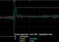
A picture is worth a thousand words, so here is one for comparison's sake:

This is what 0.05Ω or so on a low-ESR cap should look like. There is some oscillation when the step is applied due to series inductance in the wiring and cap, then the capacitor voltage step settles at about 0.3mV above its initial voltage within nanoseconds. The step is so small, it is almost lost to the scope's noise floor.
Current page: Capacitor Postmortem
Prev Page PWM Bypass Capacitor Results Next Page Do We Have A Definitive Fix?Stay on the Cutting Edge
Join the experts who read Tom's Hardware for the inside track on enthusiast PC tech news — and have for over 25 years. We'll send breaking news and in-depth reviews of CPUs, GPUs, AI, maker hardware and more straight to your inbox.
-
Nuckles_56 An interesting read, it was interesting following the process you used to troubleshoot the problemReply -
Crashman I used to do this for a living :)Reply
Don't tell my boss, I've managed to convince him that I'm only an expert at running benchmarks and writing about the results :) -
epsiloneri Disclaimers won't help. The people who will likely hurt themselves trying this are the same who lack the reading comprehension and self awareness to understand those disclaimers are directed at them. I admire you courage in publishing this.Reply
-
beetlejuicegr the truth is the paper clip and multimeter is all i can go in to psus. after all i haven't studied electricity or circuits or whatever.Reply
However i do hate to throw stuff earlier than it should, like you. -
C12Friedman I like this article and I fully agree with the conclusion. I've repaired a few PSU's but, for the most part I scavenge them anymore since I can't put them in a new system (nor would I want to) IMO they aren't really worth anything other than for on a test bench.Reply -
Mr A Daniel, I know next to nothing about electronics, and yet I could not stop reading this article. Fascinating! Thanks very much!Reply -
Urzu1000 This was a great article! It was informative, as well as interesting. Personally, I've only had one PSU fail on me so far. My brother-in-law's self-built computer had a really low-end Thermaltake PSU. 800W Bronze, and oh man, did that thing go out in a blaze of glory. Very loud popping, and smoke, and funny smells. When I ripped it out of the computer, there were burns inside the case. Miraculously, the other components remained unharmed, so I slapped in a new PSU (750W Gold Seasonic) and fired it up.Reply
Still working good, but I get black soot on my hands every time I open up that case. It's a black case, so it's hard to clean it off properly. -
Interesting article. I would have simply replaced the entire unit. You saw how to fix the failure, but how many units were damaged that you didn't see? A ticking time bomb that will eventually send some spike to your much more valuable hardware than a 10 year old PSU. Wasteful, yes. I get it. I don't like to waste either. And if it's on marginal hardware, fine. But on primary systems I'm not willing to take the risk. I'd rather throw away a 200$ part that has a 0.05$ repair solution, than risk frying 800$+ hardware.Reply
-
kalmquist "Antec's manufacturer (Channelwell in this case) got the live and neutral wires backwards, which means that in the “off” position, the neutral line gets opened and everything on the primary side becomes live instead of neutral."Reply
That's really bad--I doubt it is even legal to sell a power supply wired like that. I've never bought a CWT (Channelwell) power supply, and based on this I wouldn't buy one, except perhaps for a high end model where you might gamble that the company would exercise a bit more care.