Silverstone PB06 USB Power Bank Tear-Down
Battery Run-Down
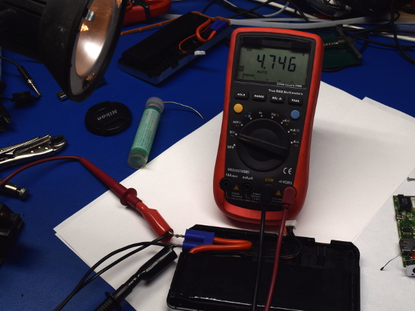
Before peeking inside the battery pack to see if it has any built-in protection, a prudent first step is to discharge beforehand. Here, I hooked the fully charged battery up to a 20W 12V halogen bulb and it remained lit with over 10V coming out of the battery for two hours. When I checked up on it again five minutes later, the battery voltage had collapsed to 4.75V with the bulb still lit, which means the battery has no built-in over-discharge protection.
Two hours at an average of 1.5A makes 3Ah of usable capacity. Since batteries are nominally rated on a 20h discharge, where they typically yield ~10% higher numbers than 2h discharge, this result agrees with the 10,000mAh (3333mAh/cell) rating.
MORE: SilverStone Stash Tour
MORE: Best Deals
Battery Top
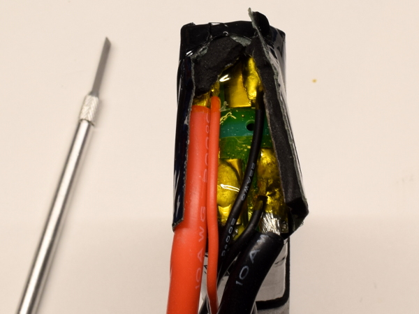
What is hidden under multiple layers of tough tape and some protective foam pads? A small circuit board covered in polyimide tape that does nothing more than act as a spacer for the lithium cells’ solder tabs, the power cables, and the main board’s cell taps. For better or worse, the 12V terminals grant you unfettered access to the underlying LiPo battery.
MORE: SilverStone Stash Tour
MORE: Best Deals
Charging Back Up
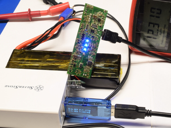
Now that the battery has been somewhat over-discharged and taped back together, it's time to see how much energy is necessary to recharge it. After five and a half hours of charging at 1.45A and 4.95V, the PB06 is still charging with its voltage creeping up through 12.3V. It needed another hour and 1.45Ah beyond this picture to reach full charge at 12.63V battery voltage. That’s 47.7Wh going in to charge a 37Wh nominal capacity battery, which yields 77.5% charging efficiency between DC-DC converter losses, battery losses, battery gauge LEDs, and anything else that might have been draining power.
MORE: SilverStone Stash Tour
MORE: Best Deals
Get Tom's Hardware's best news and in-depth reviews, straight to your inbox.
PCB Top
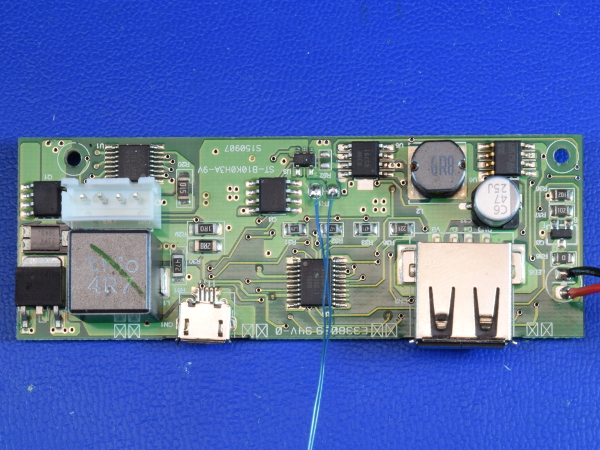
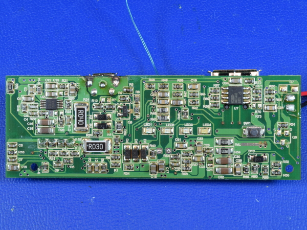
Going clockwise from the Micro-B connector, we find a high-current 4.7µH inductor, an AP9T18 N-channel FET and Z3PK2045 diode handling input voltage boosting from the input 5-9V to the battery’s 12V, with an AP4957AGM dual P-channel FET between the boost converter and battery to isolate the battery if needed. The task of monitoring cell voltages and battery current to keep the battery within healthy operating margins is handled by an SII S8254 protection circuit. Next along the power chain is an AP9410GM N-FET gating power to the output, and a G5791, which must be a buck regulator for the type-A output port. Lastly, a mystery chip labeled IN6088P11A manages the power bank’s functions.
MORE: SilverStone Stash Tour
MORE: Best Deals
PCB Bottom
On the bottom, we find two more integrated circuits. In the Micro-B area, providing the battery charger's voltage boost function, is a GMT G5322A boost controller. The other chip right under the type-A connector is a CHY100D, which happens to be a QuickCharge 2.0 voltage selection chip.
Soldering on both sides of the board looks reasonably good, though several parts (including both USB connectors) are slightly crooked and anchor point soldering for the Micro-B connector is sub-par on both sides.
MORE: SilverStone Stash Tour
MORE: Best Deals
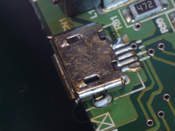
Micro-B Soldering, Top
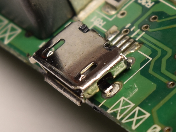
From the top side, my first unit’s factory soldering has a visible void along the edges of its shell’s mechanical tabs, a sign that solder may not be properly adhering to the shell’s metal. This could be either a cold solder joint or the result of a surface finish with poor solderability. I'd worry that it may only be a matter of time before failure if the connector is held in place by little more than friction.
MORE: SilverStone Stash Tour
MORE: Best Deals
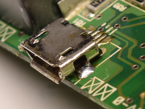
Micro-B Soldering, Bottom
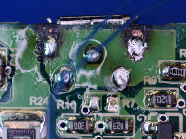
On the bottom, the top-left pad shows a fair amount of burnt flux and solder mask, with specks of missing solder mask. Around the top-right pad, we see much of the same with a whole chunk of missing solder mask between the pad and board edge. Whoever hand-soldered the connector here clearly struggled with it and ultimately still failed to produce proper-looking solder joints. This doesn’t look right for factory-new jobs.
Time to open my second PB06 and have a look at that rattling Micro-B connector. Is the solder missing? Not enough solder? Cold solder joints?
MORE: SilverStone Stash Tour
MORE: Best Deals
Micro-B Soldering, Second Unit
And the winner is unlisted answer number four: not readily solderable finish on the mechanical pins. What I found waiting for me was solder in the retention holes with no sign of any of it ever sticking to the shell’s mechanical pins. When I tried tinning the shell’s pins with my soldering iron set to 300°C, I could not get either lead-free or leaded solder to stick, even after adding RMA flux and scraping the surface. The slightly ferromagnetic shield may indicate some sort of steel.
That would explain the apparent use of excessive heat and solder flux in the first unit, which is far from ideal when you want a durable mechanical bond.
MORE: SilverStone Stash Tour
MORE: Best Deals
Reattachment
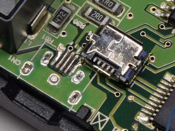
Here’s my best attempt at putting the connector back on the board using rosin mild-activated (RMA) flux and leaded solder. If you look closely at the bottom mechanical pad, the solder is forming a doughnut around the metal pin instead of sticking to it, as if the metal was repelling the solder. While this may look like a typical cold solder joint, there is nothing cold about it. I was using 350°C hot air to rework the area, and pads under the connector did reflow.
While the connector is back on and working, I have very little confidence in the long-term reliability of these mechanical joints. To me, it looks like the shell tabs are missing tin plating or other solderability-enhancing treatment.
MORE: SilverStone Stash Tour
MORE: Best Deals
Re-Reattachment
What can you do when no-clean and RMA flux fail you? Step things up a notch with acid-based flux. The day after my unconvincing attempts at re-attaching the connector, I remembered that I had a small roll of organic acid (OA) core solder and decided to give that a shot.
To avoid ruining my soldering iron tip with acid flux, I reflowed the existing solder by applying heat to the back of the board, then applied the acid-core solder to the shell pins on the top side. The result after cleaning? A great-looking solder joint. That should have been the factory standard.
Why not use acid flux all the time? Because it is more caustic, electrically conductive, and will continue eating metals away until removed, which requires more thorough cleaning.
MORE: SilverStone Stash Tour
MORE: Best Deals
-
Daniel Sauvageau For those wondering how that third unit turned out, its 12V cover is in-between the first two: tight enough not to slip out on its own, but not snug enough to stay put completely either. So far, the micro-B connector hasn't broken off from mild intentional abuse.Reply -
alextheblue For those who want jump-starting first, with a dash of USB charging, Noco's Genius Boost GB40 is solid. The GB40 is rated at 1000A "3 seconds" which falls somewhere between cranking and peak amps. They have even more powerful options too. They're pricey unless you find a good deal. Other good-looking (brand and otherwise) options I've run across that prioritize jump starting but still have decent USB 5V capability:Reply
- Omega's 80600. 350/700A peak. I've used this model. Also sold under Pro-Lift I-8006 series. 6000 rated mAh 5V capacity IIRC.
- Omega's harder-to-find 81100 unit. 400/800 amps - rated 11000 mAh
- Ravpower's RP-PB053 600A peak unit. 18000 mAh "raw"/unrated capacity.
- Ravpower's RP-PB063 1000A peak unit. 14000 mAh - rated?
- Bolt Power's D29 450/900A peak unit. 18000 unrated mAh.
- Wagan's 7506 V10 "400"/700A peak unit.
Of those probably the most interesting units is Ravpower's RP-PB063. It's still geared towards jump starting but it has faster charging than any of the other ones above - one of its USB ports even supports QC 3.0. -
Olle P Overall a nice in-depth review!Reply
Two oddities though:
1. This is NOT a 10Ah battery pack. Since the cells are connected in series it's just 3,3Ah.
2. The ripple is measured at ~9V. Shouldn't the USB output be 5.0V? -
Daniel Sauvageau Reply
Most power banks report the total combined rating of their lithium cells. Travel restrictions don't care if the cells are in series or parallel, all they care about is the total Wh or Ah capacity of the underlying cells. For the end-users, 50Wh is 50Wh regardless of series or parallel as well. When you buy a 5.2Ah power bank, you usually find a pair of 2600mAh cells in parallel but this only gives you ~4V, so you need a boost converter to get that up to ~5.1V. Since the PB06's battery voltage is 12.6V, it uses a buck regulator to bring that down to 5V or 9V instead.19542706 said:Overall a nice in-depth review!
Two oddities though:
1. This is NOT a 10Ah battery pack. Since the cells are connected in series it's just 3,3Ah.
2. The ripple is measured at ~9V. Shouldn't the USB output be 5.0V?
I suppose I should have tested at 5V too instead of 9V Quick Charge. Same inductor and switching frequency though since all the QC voltage selection chip does is change the switching regulator's feedback voltage divider, so ripples would still be quite significant at about half as much. -
Olle P Reply
There's a HUGE difference between watthours (stored energy) and amperehours (battery capacity), since the former takes the voltage into account.19543501 said:
Most power banks report the total combined rating of their lithium cells. Travel restrictions don't care if the cells are in series or parallel, all they care about is the total Wh or Ah capacity of the underlying cells. For the end-users, 50Wh is 50Wh regardless of series or parallel as well.19542706 said:1. This is NOT a 10Ah battery pack. Since the cells are connected in series it's just 3,3Ah.
The package clearly states 10 Ah, which it's not.
It's 3.3 Ah, 36 Wh.
