EVGA SuperNOVA 650 GM PSU Review: Big Power In A Small Form Factor
Why you can trust Tom's Hardware
Transient Response Tests
Advanced Transient Response Tests
For details on our transient response testing, please click here.
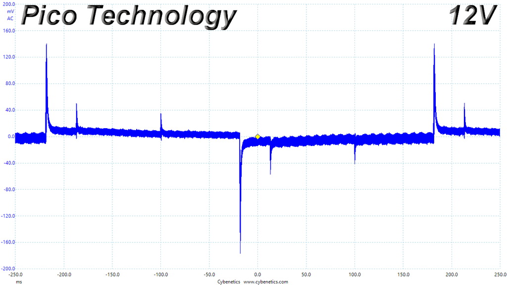
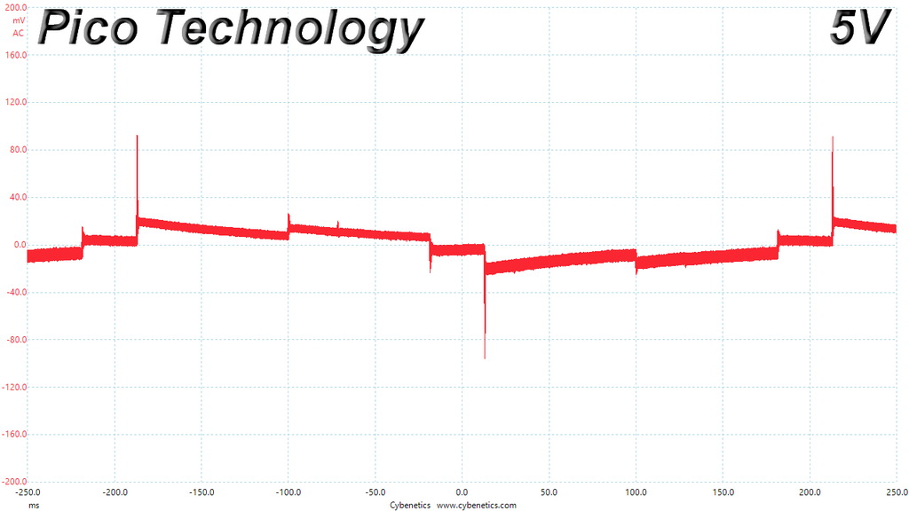
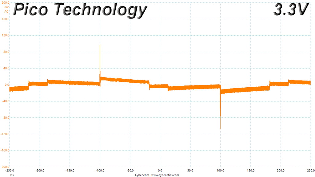
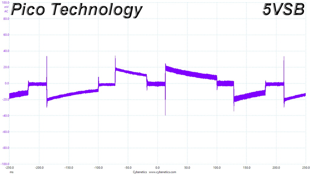
Ιn these tests, we monitor the 650 GM's response in several scenarios. First, a transient load (10A at +12V, 5A at 5V, 5A at 3.3V, and 0.5A at 5VSB) is applied for 200ms as the PSU works at 20 percent load. In the second scenario, it's hit by the same transient load while operating at 50 percent load.
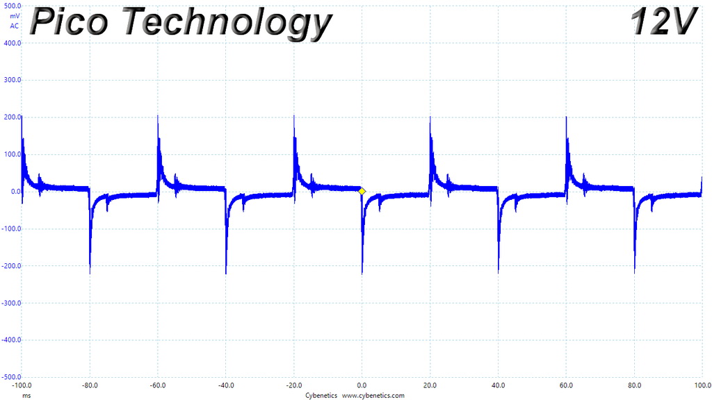
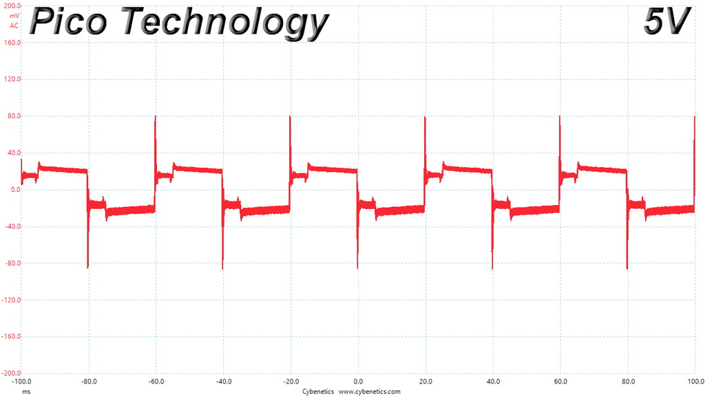
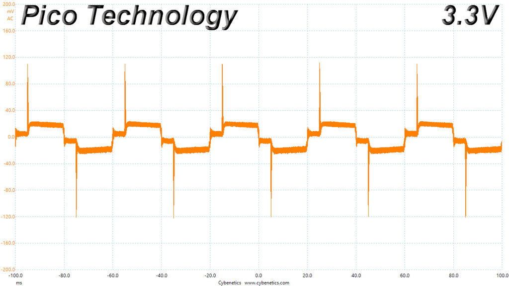
In the next sets of tests, we increase the transient load on the major rails with a new configuration: 15A at +12V, 6A at 5V, 6A at 3.3V, and 0.5A at 5VSB. We also increase the load-changing repetition rate from 5 Hz (200ms) to 50 Hz (20ms). Again, this runs with the PSU operating at 20 and 50 percent load.
The last tests are even tougher. Although we keep the same loads, the load-changing repetition rate rises to 1 kHz (1ms).
In all of the tests, we use an oscilloscope to measure voltage drops caused by the transient load. The voltages should remain within the ATX specification's regulation limits.
These tests are crucial because they simulate the transient loads a PSU is likely to handle (such as booting a RAID array or an instant 100 percent load of CPU/GPUs). We call these "Advanced Transient Response Tests," and they are designed to be very tough to master, especially for a PSU with a capacity of less than 500W.
We should note that the ATX spec requires for capacitive loading during the transient rests, but in our methodology we chose to apply the worst case scenario with no extra capacitance on the rails.
Get Tom's Hardware's best news and in-depth reviews, straight to your inbox.
Advanced Transient Response at 20 Percent – 200ms
| Voltage | Before | After | Change | Pass/Fail |
|---|---|---|---|---|
| 12V | 12.043V | 11.866V | 1.47% | Pass |
| 5V | 5.081V | 4.983V | 1.93% | Pass |
| 3.3V | 3.277V | 3.169V | 3.30% | Pass |
| 5VSB | 5.054V | 5.015V | 0.77% | Pass |
Advanced Transient Response at 20 Percent – 20ms
| Voltage | Before | After | Change | Pass/Fail |
|---|---|---|---|---|
| 12V | 12.040V | 11.817V | 1.85% | Pass |
| 5V | 5.075V | 4.987V | 1.73% | Pass |
| 3.3V | 3.271V | 3.149V | 3.73% | Pass |
| 5VSB | 5.105V | 5.044V | 1.19% | Pass |
Advanced Transient Response at 20 Percent – 1ms
| Voltage | Before | After | Change | Pass/Fail |
|---|---|---|---|---|
| 12V | 12.042V | 11.818V | 1.86% | Pass |
| 5V | 5.082V | 4.974V | 2.13% | Pass |
| 3.3V | 3.277V | 3.164V | 3.45% | Pass |
| 5VSB | 5.056V | 4.990V | 1.31% | Pass |
Advanced Transient Response at 50 Percent – 200ms
| Voltage | Before | After | Change | Pass/Fail |
|---|---|---|---|---|
| 12V | 12.023V | 11.848V | 1.46% | Pass |
| 5V | 5.060V | 4.959V | 2.00% | Pass |
| 3.3V | 3.253V | 3.135V | 3.63% | Fail |
| 5VSB | 5.023V | 4.986V | 0.74% | Pass |
Advanced Transient Response at 50 Percent – 20ms
| Voltage | Before | After | Change | Pass/Fail |
|---|---|---|---|---|
| 12V | 12.023V | 11.771V | 2.10% | Pass |
| 5V | 5.061V | 4.951V | 2.17% | Pass |
| 3.3V | 3.253V | 3.131V | 3.75% | Fail |
| 5VSB | 5.024V | 4.962V | 1.23% | Pass |
Advanced Transient Response at 50 Percent – 1ms
| Voltage | Before | After | Change | Pass/Fail |
|---|---|---|---|---|
| 12V | 12.023V | 11.830V | 1.61% | Pass |
| 5V | 5.061V | 4.951V | 2.17% | Pass |
| 3.3V | 3.254V | 3.129V | 3.84% | Fail |
| 5VSB | 5.024V | 4.973V | 1.02% | Pass |
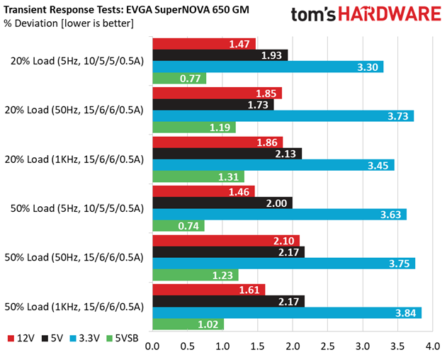
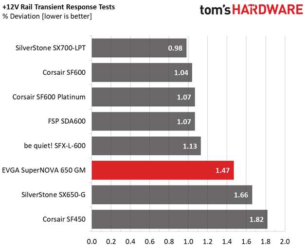
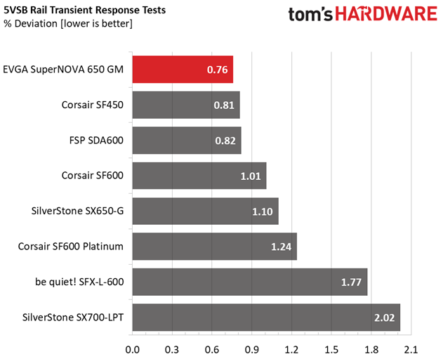
Deviations on the +12V rail are a bit higher than what we like to see. Ideally, they should be close to 1%.
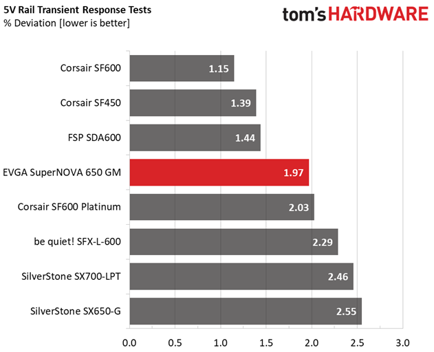
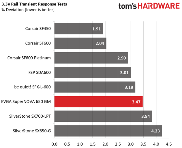
The response to transient loads is good at 5V and 5VSB, although it's mediocre at 3.3V where EVGA's 650 GM fails three tests. Deviations on the 3.3V rail aren't terrible. The bigger issue is not-so-tight load regulation, which permits a nominal voltage lower than 3.3V in the 50% load scenario.
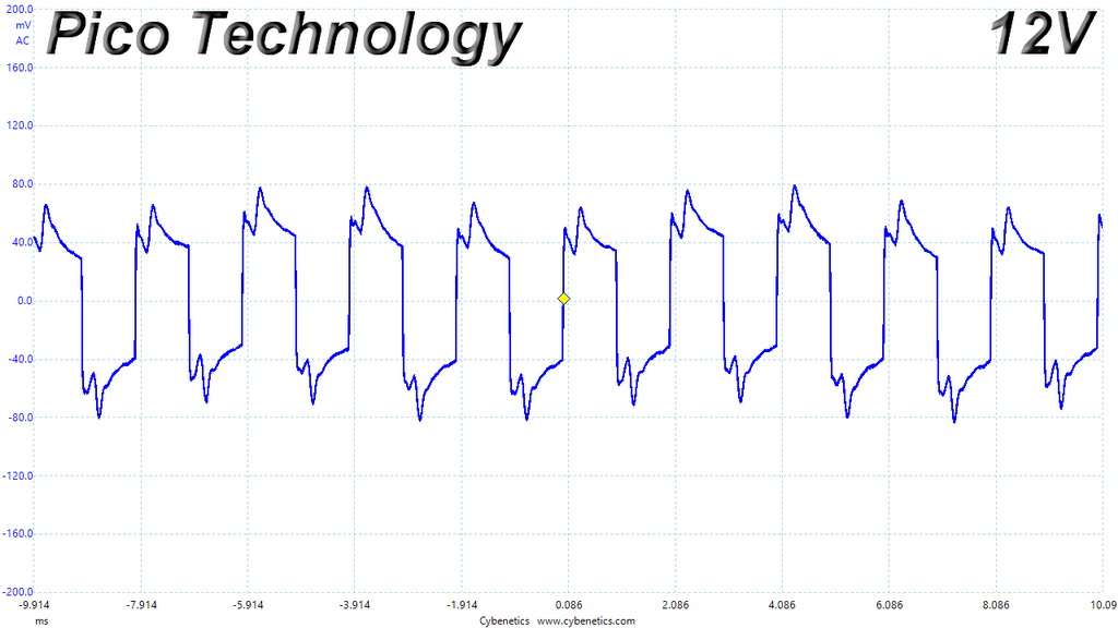
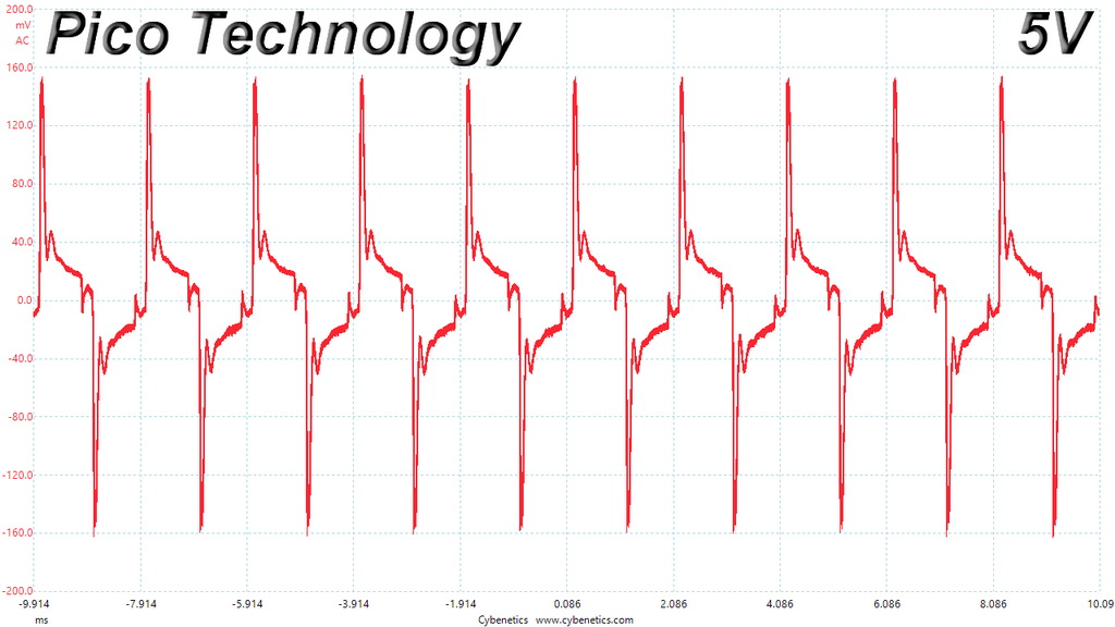
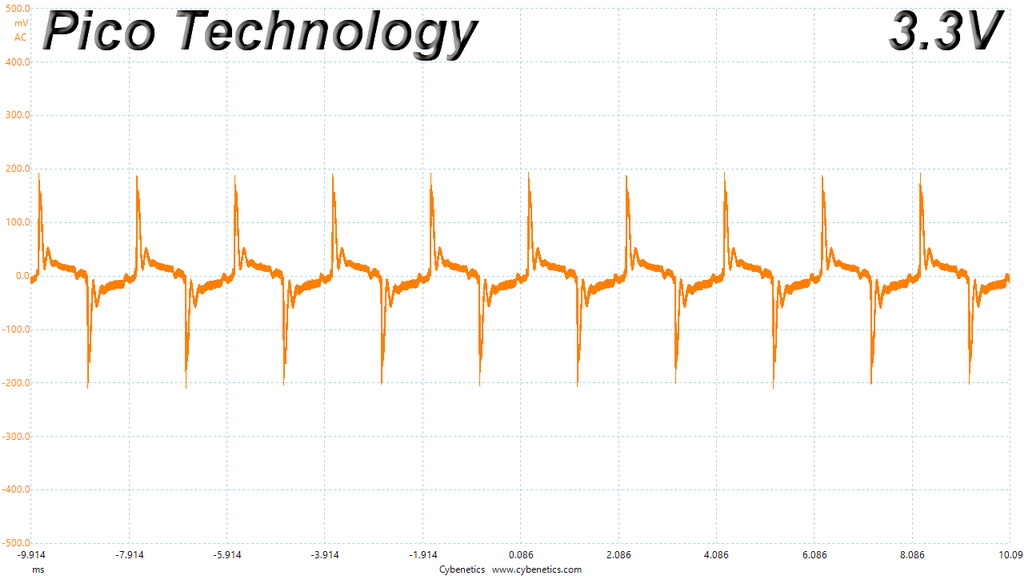
Here are the oscilloscope screenshots we took during Advanced Transient Response Testing:
Transient Response At 20 Percent Load – 200ms
Transient Response At 20 Percent Load – 20ms
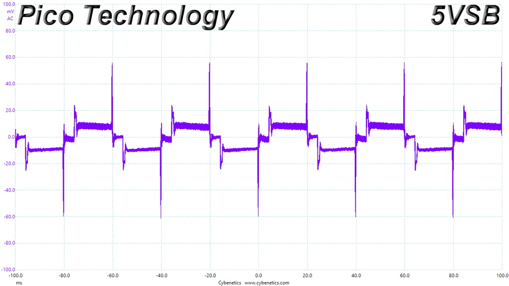
Transient Response At 20 Percent Load – 1ms
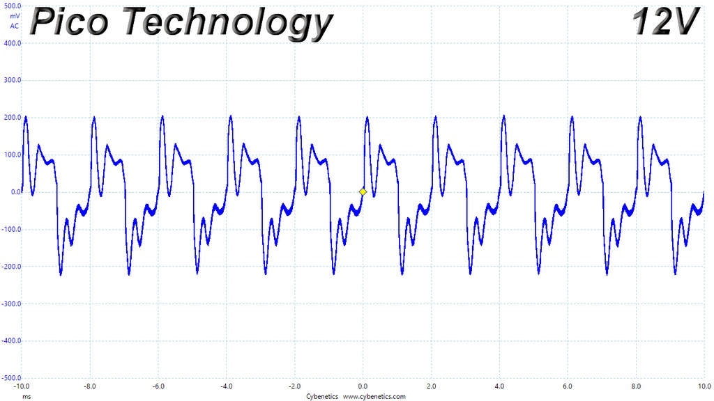
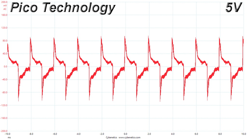
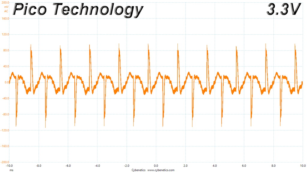
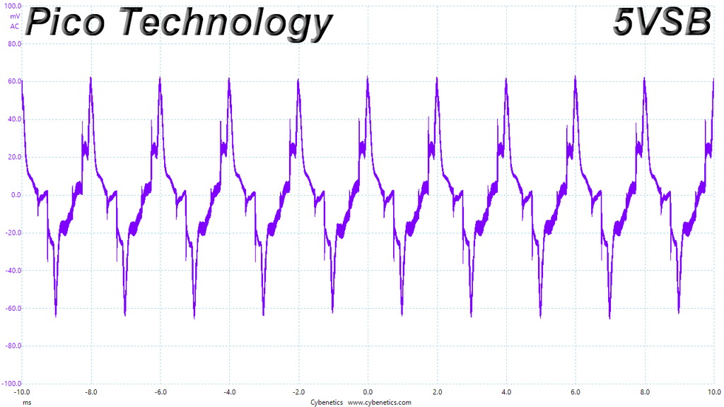
Transient Response At 50 Percent Load – 200ms
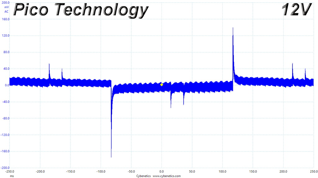
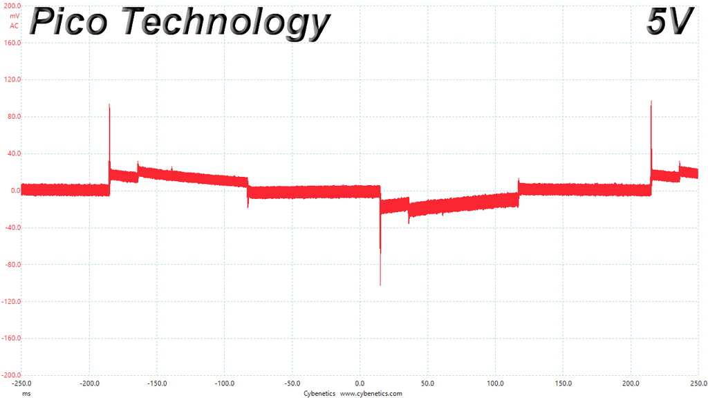
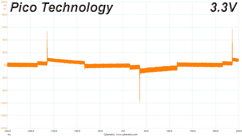
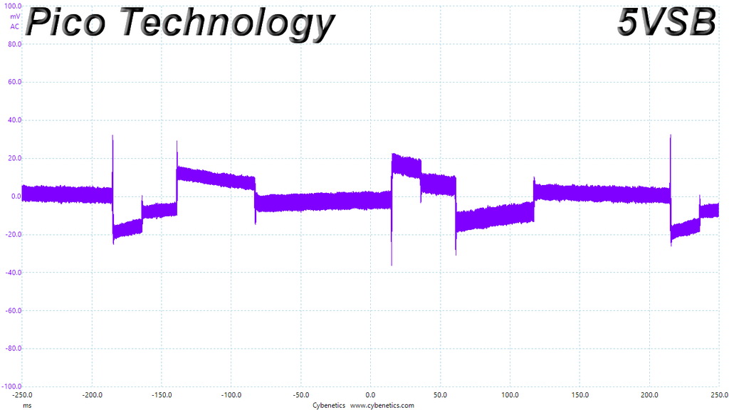
Transient Response At 50 Percent Load – 20ms
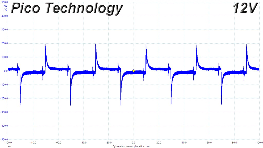
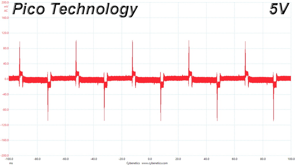
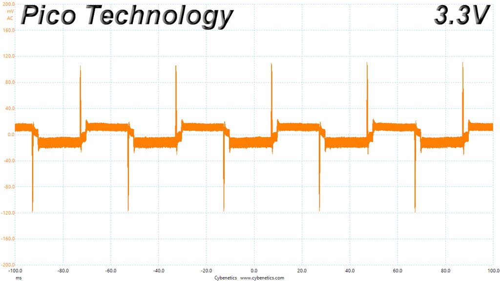
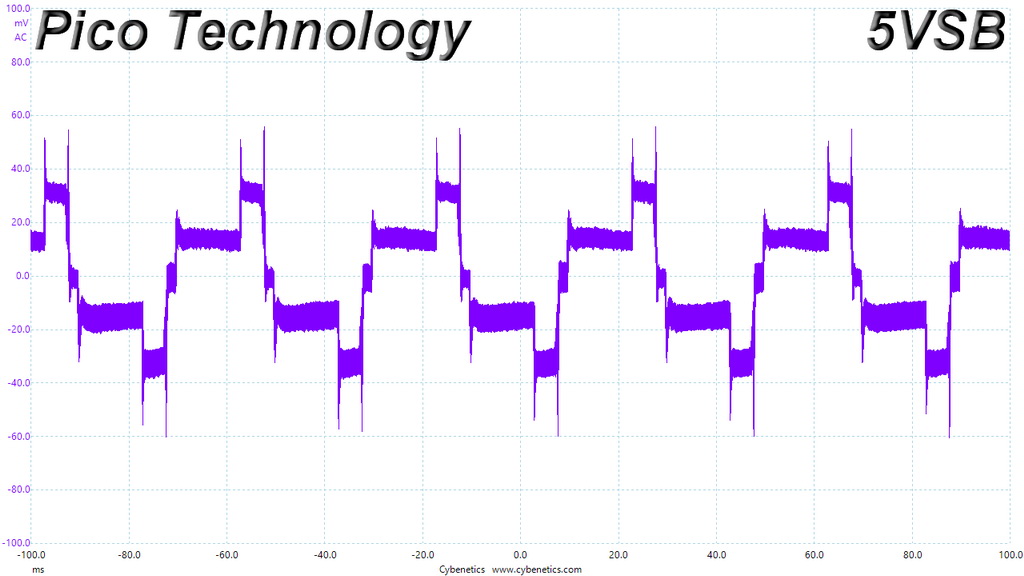
Transient Response At 50 Percent Load – 1ms
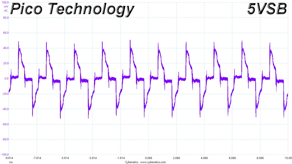
Turn-On Transient Tests
In the next set of tests, we measure the 650 GM’s response in simpler transient load scenarios—during its power-on phase.
For our first measurement, we turn the power supply off, dial in the maximum current the 5VSB rail can handle, and switch the PSU back on. In the second test, we set the +12V rail's maximum load and start the PSU while it is in standby mode. In the last test, with the PSU switched completely off, we dial in the +12V rail's maximum load before restoring power. The ATX specification states that recorded spikes on all rails should not exceed 10 percent of their nominal values (+10 percent for 12V is 13.2V, and 5.5V for 5V).
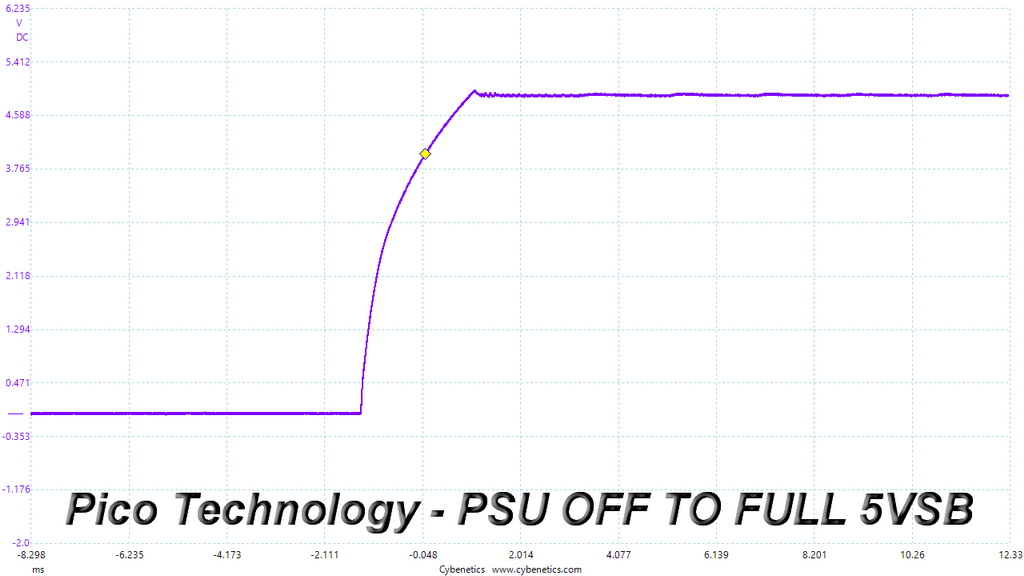
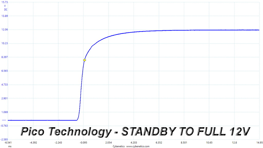
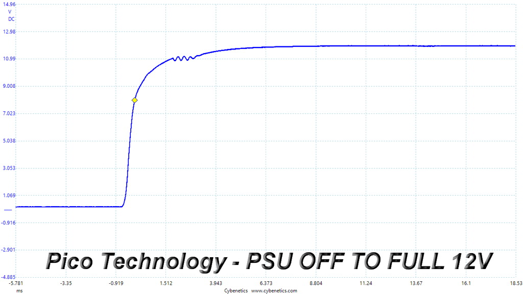
There is a tiny voltage overshoot on the 5VSB rail and some small waveform saws in the last test. Overall, though, the results are good.
MORE: Best Power Supplies
MORE: How We Test Power Supplies
MORE: All Power Supply Content
Current page: Transient Response Tests
Prev Page Cross-Load Tests and Infrared Images Next Page Ripple Measurements
Aris Mpitziopoulos is a contributing editor at Tom's Hardware, covering PSUs.